|
Call: +44(0)1234 841221 E-mail: [email protected]
Air
Conditioning Inverter Compressor Tester
Special offer It is best to test
inverters with no compressors connected especially if you expect
the compressor is at fault. But if you remove the wires from the
compressor and try to run the systems a fault will be displayed the
fault is caused by the inverter PCB being able to detect whether a
compressor is connected or not. Most modern inverters are able to detect
whether the compressor has been disconnected in only a few seconds
making testing very difficult. Testing can be done
in two ways: Firstly, the hard
way…… You will need a
digital multi meter with a min max function, Turn off the power Disconnect the
compressor either from the PCB or at the compressor terminals. Connect
your meter to two of the phases (Red to blue) set your meter to record
max and min voltage Power up and Start
the unit Let the inverter start and watch the Voltage rise. Record the
maximum Voltage. The inverter will stop after a few seconds and the
voltage will fall to 0. Swap the leads to measure the next two phases
(Red to Yellow). Measure as before Repeat for the last two phases Blue
to Yellow. The readings of maximum voltage should be the same for all 3
measurements if not the inverter is faulty, the PCB will need replacing. If the readings are
equal the Inverter is healthy and the compressor will need replacing. And the easy
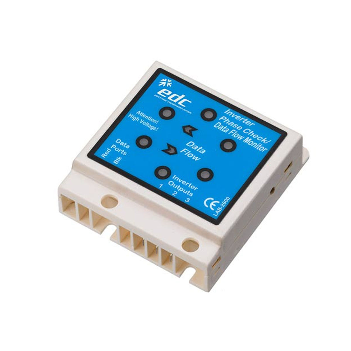
way...... You will need an
Inverter tester, Turn off the power. Disconnect the compressor lead from
the compressor terminals. Connect your inverter tester to all 3 leads
(polarity is not important) Power up and Start the unit. Let the
inverter start and watch the LED's. All 6 must light up
and should be of equal brightness The inverter will
stop after a few seconds and the LED's will go out If you miss the
LED's (they will only light for a couple of seconds) the unit will try
to start again 3 times with a 3 minute delay between each test If all 6 LED's DON’T
light up the inverter is faulty, the PCB will need replacing. If the LED's all
light up the Inverter is healthy and the compressor will need replacing.
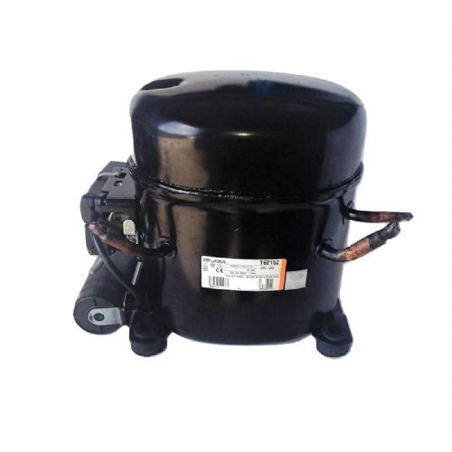
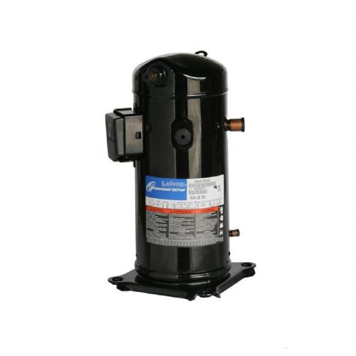
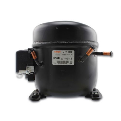
We
supply genuine refrigeration compressors and air conditioning
compressors world-wide including Europe, USA, Canada, Asia, Australia,
Asia, Central and South America and Africa. World and European brands of
compressors 240V / 50Hz including, Danfoss, Copeland, Aspera, Dorin,
Bitzer, Tecumseh, Maneurop, L'unite Hermetique and many more. Many units
on popular gases such as R404, R134a, R22, R407c and R410a.
We also distribute the following range of refrigerant compressors gases:
R404,
R134a, R22, R32, R407c, R407A, R410a and many more Refrigeration
Compressor world-wide / European Brands: L'unite
Hermetique refrigeration compressor (Full Range Here) Tecumseh
refrigeration compressor (Full Range Here) Aspera
refrigeration compressor (Full Range Here) Copeland
refrigeration compressor (Full
Range Here) Danfoss
refrigeration compressors (Full
Range Here)
Contact Us: Sales
UK: +44 (0)1234 841221
|