


CHECK YOU HAVE RECEIVED
Your Graduate Green PowerEd packing case contains the following items:-
1. Rutland WG913 Windcharger 1 x Main Generator Assembly 6 x Aerofoil Blades 1 x Nose Dome 1 x WG913 Parts Bag containing:- 24 x No.10x25 Blade Screws 3 x M5x25 Nylon Screws 2 x M10x16 Button Skt Screws 2 x M10 Int Shake-proof Washers 1 x 2 Way Latching Plug and Socket 1 x 6mm Allen Key 2. Solar Panel 1 x BP365 12v 65w PV Module. 3. Solar Panel Mounting Kit Refer to Section 6 -Solar Panel Mounting Kit Assembly 4. Power Monitor 1 x Graduate Green PowerEd Monitor 5. Weather Sensor Assembly 1 x Weather Sensor Arm fitted with Anemometer, Light/Temperature Sensors, Junction Box and Mounting Plate 1 x Weather Sensor Fixing Kit Bag containing:- 2 x M8 x 50mm U bolts c/w Clamps 4 x M8 Int Shake-proof Washers 1 x ‘D’ Connector 9 Way Plug 1 x ‘D’ Connector Cover 1 x Wind direction Vane (Optional) 6. Lead-Acid Batteries 2 x 70 Ah, Deep Cycle, Charged Lead Acid Batteries 2 x Pairs Clip-on Battery Terminals (Red=Positive/Blue=Negative) 7. Cables 1 x 50m 2 Core Power Cable 2.5mm² 1 x 25m 6 Core Data Cable 1 x 25 Way Cable c/w ‘D’ Connectors (PC to ADC-11) 1 x USB Cable (ADC-11 to PC) 8. Miscellaneous 1 x CD (PicoLog Software) 1 x CD (Power Monitor configuration files and Owner’s Manual) 1 x Picolog 1012 Data LoggerNote: Occasionally components may be substituted, where alternatives are used follow the assembly instructions supplied with that component.
INTRODUCTION
This manual contains important information about your Graduate Green PowerEd power generation and weather monitoring system. We recommend that you familiarise yourself with the contents of this and other manuals supplied before and during installation.
The Graduate Green PowerEd system generates power from a Rutland Windcharger and a solar (photovoltaic) panel and stores this power in lead-acid batteries. The batteries are used as a 12V-energy source to power low energy 12V appliances or power can be converted through an inverter for mains appliances. Additionally the Graduate Green PowerEd system monitors, records and displays the following information:- • Windspeed (Metres/second) • Daylight level (Lux) • Temperature (°C) • Windcharger output (Amps) • Windcharger power in (Watts) • Solar panel output (Amps) • Solar Panel power (Watts) • Battery voltage (Volts) • Load circuit current draw (Amps) • Load circuit power (Watts) • Optional Wind Direction (Degrees)It is very important that the various components of the Graduate Green PowerEd system are mounted correctly, both individually and relative to each other and that all the electrical connections are accurately made. This manual has been carefully drafted to help you to achieve this easily and to prevent damage or reduced operating effectiveness that follows faulty installation. Please read and understand each section before commencing installation.
GENERAL GUIDELINES & WARNINGS!
There are general guidelines and warnings relating to each of the following:
Rutland 913 Windcharger BP365 Solar (PV) Panel Power Monitor Weather Sensors BatteriesWarning! Please read each section before commencing assembly or installation!
Rutland 913 Windcharger
• Mounting pole outside diameter MUST NOT exceed 48.5mm for at least the top 0.5m. Larger diameter poles must not be used, as this will reduce the tower to blade clearance. In high wind conditions this could cause damage to the Windcharger by allowing the blade to come into contact with the mounting pole. A broken blade will cause turbine imbalance with consequent damage. Temporarily the Windcharger can be operated with 3 equally spaced blades.
• When turning, the Windcharger is capable of generating voltages in excess of the nominal voltage. The turbine must never be allowed to rotate unless it is electrically connected to a regulator or batteries. Connecting an open circuit running turbine to the electrical system can cause serious damage to system components owing to excessive voltage. Caution must be exercised at all times to avoid electric shock.• Stopping the turbine – this may be necessary to undertake maintenance. If possible stopping the turbine should be done in low windspeed conditions. Rotating or orienting the tail fin upwind can slow the turbine; this will slow the turbine sufficiently for it to be safely secured to the pole with rope. Avoid leaving the Windcharger tied up for any period of time, we recommend that it either be covered to give protection from the weather or removed and stored in a dry location.
• No attempt to repair the system should be made until the Windcharger is restrained from turning.
• The Windcharger is fitted with ceramic magnets, which can be damaged by heavy handling. The main generator assembly should be treated with care during transit and assembly.
•
It is essential to observe the correct polarity when connecting the Windcharger and all other components into an electrical circuit. Reverse connection may cause serious damage to the system components and incorrect installation will invalidate the warranty.•
High winds – in high winds the windcharger’s built-in thermostat may operate to prevent the generator overheating. In this mode the output will cease and the turbine will temporarily speed up until such time as a cool enough temperature is reached and the generator is once again connected and charging. This may be seen to cycle in prolonged high winds particularly in high ambient temperatures. If safely accessible you may prefer to temporarily secure the turbine• When storm winds are forecast the turbine can be restrained to minimise wear and tear, this may prevent damage occurring from a combination of high winds and turbulence. The warranty is not valid in the case of force majeur conditions or wind speeds.
• If in doubt, refer to your dealer, a competent electrical engineer or the manufacturer.
• Any unauthorised alteration to the Windcharger will invalidate the warranty.
• Position the Windcharger so that no more than 20m of electrical cable is needed to run from it to the Power Monitor using the power cable supplied. If a greater distance is necessary alternative cable must be used; refer to table in the Cable Preparation section.
BP 365 Solar (PV) Panel
• The solar panel will generate a voltage when exposed to sunlight. We recommend covering the front surface of the solar panel with an opaque cloth until the module is properly mounted and connected to the Power Monitor to avoid handling live wires.
• Solar panels must be handled with care; the panel is constructed from tempered glass, it is fragile and is liable to shatter if knocked or bent. We recommend that the panel is always handled by its longer sides.
• Do not attempt to disassemble the module. Any alteration to the panel will invalidate its warranty.
• Position the solar panel so that no more than 20m of electrical cable is needed to run from it to the Power Monitor using the power cable supplied. If a greater distance is necessary alternative cable must be used; refer to table in the Cable Preparation section.
Power Monitor
• The Power Monitor is not weather proof; it must be situated in a dry position protected from the weather.
• The Power Monitor is electronically sensitive and calibrated for use with only the Rutland Windcharger and solar panel provided, the connection of other components may cause damage and will invalidate the warranty.
• The Power Monitor will be permanently damaged if at any time any of the active components, i.e. batteries, Windcharger, solar panel or loads, are connected with reverse polarity. Maximum care must be exercised that the correct polarity is chosen when making any connection.
• None of the active elements must be connected to the Power Monitor whilst they are live. The Windcharger or the solar panel must not be generating power and the battery connectors must not be connected to the batteries as they are connected to the Power Monitor.
• Position the Power Monitor within 2m cable run distance from the battery bank and within the lengths of the interconnection cables supplied from the PC.
• The Power Monitor case is internally connected to ground potential, it is important that no live conductors come into contact with the case otherwise damage to the electronics may occur.
• When installed, ensure that the case is not in contact with any earthed metalwork since this may result in inaccurate readings.
Weather Sensors
• The weather sensors are delicate devices. Care must be taken when fixing the weather sensor arm to the tower that the elements of this component are not knocked and damaged.
Lead-Acid Batteries
• Caution must be exercised at all times when handling batteries as they are potentially hazardous. Only qualified persons should undertake connection and maintenance.
• Two sets of battery terminals are supplied for connection, these must be used as follows:
RED = Positive + BLUE = Negative –
• DANGER! NEVER CONNECT THESE IN REVERSE, AS SERIOUS DAMAGE WILL OCCUR.
PRINCIPLE OF OPERATION & COMPONENT SPECIFICATIONS
Rutland Windcharger
The Rutland 913 Windcharger is designed to operate in a clear airflow and generate power into a battery from wind speeds of 3 metres per second (m/s) and above. The 12V DC power generated relates directly to the windspeed at the turbine and is transmitted down the tower to the Power Monitor via the power cable supplied.
The Windcharger’s generator is thermally protected and during periods of high wind the Windcharger may be seen to accelerate and power is cut off for a period of time to allow the generator to cool. In gale force winds it is advisable to prevent the turbine from turning by restraining the blades. See “General Guidelines & Warnings” section.
Rutland 913 Performance Graph
Solar (PV) Panel
The BP 365 type photovoltaic panel is designed to be oriented to South facing (in the Northern hemisphere) and pitched at an angle according to location to give optimum performance. When exposed to sunlight it will generate 12V DC power into a battery, up to a maximum of 65W according to the strength of solar radiation. Power is transmitted to the Power Monitor via the power cable supplied. A mounting kit with brackets is supplied to fix the panel to the tower.
The characteristics of the BP Solar crystalline PV module are given in the table overleaf. The readings refer to ‘Standard Test Conditions’; an irradiance of 1kw/m2 , AM 1.5 spectrum, cell temperature 25o C.
|
Characteristic |
Value |
|
Module Nominal Voltage |
12V |
|
Module rated power |
65W |
|
Module open circuit voltage |
22.1V |
|
Module short circuit current |
3.99A |
|
Module voltage at max power |
17.6V |
|
Module current at max power |
3.69A |
|
Length |
1111mm |
|
Width |
502mm |
|
Height |
50mm |
Weather Sensors
The weather sensor assembly should be positioned close to the Windcharger and solar panel. It measures wind speed, wind direction (optional), light level and temperature, information is transmitted via the data cable to the Power Monitor. Note that this equipment is very delicate and must be handled with care.
|
Anemometer: |
Rotating cup type, Windspeed range 1m/s – 35m/s |
|
Temperature: |
NTC Thermistor, calibrated –20°C to +40°C. |
|
Light Level: |
LDR calibrated 0 lux to 30000 lux. |
Power Monitor
The Power Monitor has a multitude of functions as follows:-
• Charge controller – it senses the battery voltage and as the batteries approach their fully charged state it reduces the speed of the turbine and reduces the power from the solar panel to prevent the batteries from becoming overcharged. When the battery voltage has reduced owing to the battery power being partially consumed the windcharger and solar panel will automatically recommence charging. When the voltage controller is operating the Red LED on the front panel will illuminate.
Note: The Power Monitor does NOT protect against excessive battery discharge.
It is the responsibility of the user to disconnect the load when necessary. (The battery voltage channel in PicoLog has an alarm to warn of low battery voltage refer to section “Pico Software Installation and Set-up” if you wish to set this)
• WG Current Ammeter – Analogue 1-10A ammeter indicates the actual current being generated by the Windcharger.
• PV Current Ammeter – Analogue 0-5A ammeter indicates the actual current being generated by the solar panel.
• Load Current – Analogue 0-10A ammeter indicates the current being drawn from the battery to supply any load appliances if connected. The maximum allowable draw of current through the Power Monitor is 10A. Always check the power rating of any appliance to be connected.
• Battery Voltage – Analogue 0-20V voltmeter indicates battery voltage.
• Protection fuse – this is built into the controller and is accessible via the access plate. It is an ATO (automotive) type 20A rated fuse.
Graduate Green PowerEd Owners Manual & Installation Guide
• Connector block – the connector block is accessed by removing the cover plate allowing easy interconnection of the system. When wiring in the external components (Windcharger, solar panel, battery and load) follow the legend printed on the circuit board.
• Output to PC – the Power Monitor is connected via the D-connector, (type 25 pin D25 Male) to the Picolog 1012, this is in turn connected via the USB cable to the PC (computer). It converts and records information and in conjunction with the software this is viewed on the PC.
• Weather Sensors Input Connector – this transmits information from the weather sensors to the A to D converter via the data cable supplied.
Batteries
Two deep cycle batteries are supplied, ready charged. Each is a minimum capacity of 70 Ampere hours (Ah) @ C20 rate. These are to be connected in PARALLEL to achieve a capacity of 140 Ah @ 12V DC. To ensure long life batteries must not be over-charged or excessively discharged. The Power Monitor provides overcharge protection and continuously displays the battery voltage. The user must ensure that the batteries are not excessively discharged. Ie do not allow the voltage to fall below 10.5v.
Caution must be exercised at all times when handling batteries as they are potentially hazardous. Only qualified persons should undertake connection and maintenance. Permanent connections should always be made to the battery terminals using the two sets of battery terminals supplied.
RED = Positive + BLUE = Negative -
DANGER! NEVER CONNECT THESE IN REVERSE AS SERIOUS DAMAGE WILL OCCUR.
Software
This is supplied in compact disc (CD) format. See section “Pico Software Installation and Set-up”. PicoLog: Minimum requirement Windows XP Service Pack 2 (32 Bit) or Windows Vista (32 or 64 Bit). A CD is provided with Power Monitor “Configuration files”.
Hardware
Minimum processor requirement Pentium II or equivalent. Recommended 2GHz Pentium IV or equivalent. Minimum memory 64 MB (XP) or 512 MB (Vista) Recommended 256 MB (XP) or 1GB (Vista) Ports must be USB 2.0 compliant
OTHER EQUIPMENT/TOOLS YOU WILL NEED
To complete the installation of your Green PowerEd System you will need the following equipment or tools as follows:-
• Tower - See recommendations in “System Assembly” section • Suitable wire strippers for 2-core power cable and 6 core screened data cable. • Phillips(cross-head)screwdriver • Large flat blade screwdriver • Small terminal screwdriver • 2 x 13mm ring or open-ended spanner/wrench • Sharp knife • Adjustable spanner/wrench • Soldering Iron • Suitable wall fixings for Power Monitor • Power DrillSELECTING THE SITE
A suitable outdoor location for the tower holding the Windcharger, solar panel and weather sensors and another indoor location for the Power Monitor, PC (computer) and batteries should be identified prior to commencing installation.
Tower Location Considerations (outdoor components)
The location and height of the tower will be the major factor in the overall performance of your system. The smooth flow of wind over land is often interrupted by a multitude of obstructions causing wind sheer and turbulence. Wind sheer describes the interference between the fast moving upper air and the slow moving air close to the ground and the resulting decrease in average wind speed as one gets closer to the ground. Turbulence is caused by the wind passing over obstructions such as trees and buildings. Both wind sheer and turbulence diminish with height and can be overcome simply by putting the Windcharger sufficiently high above them. It is therefore essential that the Windcharger should be located in an area as free as possible from disturbed wind flow. Bear in mind that downwind obstructions can be as detrimental to performance as upwind obstructions.
The solar panel should installed South facing and should not be shaded. The weather sensor arm should be positioned along an East-West axis with junction box lid facing South. Power Monitor, Picolog 1012, PC & Batteries Considerations (indoor components) Power Monitor to battery cable run should not exceed 2m to avoid excessive voltage drop. The PC should be located within reach of the Power Monitor and Picolog 1012 using the cables supplied.
Proximity of Outdoor to Indoor Components Identify a suitable route for the cables from the top of the tower to the Power Monitor, providing adequate protection from mechanical damage where necessary. The maximum cable run should be 20m, greater distances are possible but alternative power cable is required. Refer to table in the
Cable Preparation section.SYSTEM ASSEMBLY
We strongly recommend that the system is assembled in the following sequence. Although it is advisable to prepare cable lengths when the tower is initially installed
NO electrical connections should be made between elements before they are all assembled. Always restrain the Windcharger from turning and cover the solar panel until final electrical connections have been made.1. Tower/Mounting Pole (Not Supplied) We recommend that the Windcharger, weather sensors and solar panel be mounted in one of the following ways:-
a) Using a 6.5m (21’) long galvanised steel tube (Inside Diameter 41mm, Outside Diameter not to exceed 48.5mm), fixed vertically and supported by 4 sets of guy lines with the following component specification:-
• Guy wires minimum of 4mm (0.16”) diameter
• Rigging Screws minimum 5mm (0.20”) diameter
• Shackles minimum 5mm (0.20”) diameter
• All components galvanised or stainless steel
• Fit all looped guy wires with thimbles and fit minimum of 3 rope grips
• All ground fixings must be suitable according to ground conditions We recommend the vertical pole be pivoted to allow easy access for maintenance. Two examples of pivoting systems, gin pole pivot and centre pivot are illustrated in Figures 1 and 2.
b) Mounting a pole to the external elevation of a building. It is important to consult a Civil Engineer prior to considering this type of installation to ensure the integrity of the structure and the building. The pole must stand as high as possible, minimum 2m, above the building to allow unshielded exposure for the Windcharger, solar panel and weather sensors. The length of unsupported pole above the uppermost support must be 2m maximum. (Note: the Windcharger may transmit some vibration/noise through the building if mounted in this way) See Figure 3.
2. Tower Preparation
We recommend the following is carried out with the tower at ground level. The post adapter fitted to the Windcharger is designed to fit inside a standard 41mm (1⅝”) internal diameter tube. The adapter is provided with a flat on one side to clear the weld seam on seamed tube.
a) Mark and centre-punch two positions diametrically opposite, at 90° to the pipe seam if necessary, 20mm from the top of the tube. See Figure 4.
b) Drill two holes 10.5mm in diameter on centre-punch positions.
c) Position the Windcharger on the tower ensuring the flat on the post adapter aligns with the pipe seam if necessary. Check the two M10 x 16mm button socket screws and shake-proof washers provided can be fitted. Remove Windcharger until cables have been fitted at a later stage.
d) It is recommended that the cables are routed down the inside of the mounting pole. Holes will be needed to allow the weather sensor and solar panel cables to enter the pole as close as possible to the components. A suitable grommet must be fitted to prevent chafing to the cables.
Always erect the tower into it’s final position and check all guys, connections etc. are correct before finally fitting the Windcharger, solar panel and weather sensor assembly. Lower the tower again in order to fit the cables.
3. Cable Preparation
a) Power Cable (Windcharger/Solar Panel to Power Monitor) - Using the 2.5mm² two core power cable supplied the maximum cable length between Windcharger/solar panel and power monitor should be 20m (65’). If this distance is greater then alternative cable should be used. See Table below.
Cut two lengths of cable the distance between the power monitor and Windcharger/solar panel.. Thread the Windcharger and solar panel cables through the pole and any wall, conduit etc. to the location of the power monitor. Ensure exposed cables are protected from mechanical damage. Do not make any electrical connections at this stage.
b) Data Cable (Weather Sensors to Power Monitor) – Run the six core screened cable supplied from the final position of the weather sensor assembly terminal box thorough the pole and any wall, conduit etc to the location of the Power Monitor. Ensure exposed cables are protected from mechanical damage. Do not make any electrical connections at this stage.
4. Windcharger Assembly
a) Place the generator assembly on a flat surface hub-side down.
b) Position the blade as shown in Figure 5. The blades will only fit one way round. Insert the protrusion at the trailing edge of the blade root fixing first into the socket to align with the corresponding recess in the blade socket. The blade can then be inserted with a lever action. Gentle assistance with a soft-faced mallet may be required.
c) Four screws are required for each blade. Secure each blade with two of the four special self-tapping screws provided by inserting each in turn through the cut-out in the nacelle, rotating the generator each time until the holes align.
d) Fit the remaining blade screws from the front of the generator hub. Caution! -It is essential that 4 screws are fitted per blade!
e) Check the tightness of all screws (Do not over-tighten).
f) Fit the plastic nose dome in position on the front of the generator hub and secure in place with the three M5 x 25 nylon screws provided.
5. Solar Panel Preparation
a) Open the junction box lid on the rear of the solar panel.
b) Use a sharp knife to remove a “knock-out” in the position where cable entry is required.
c) Fit the cable gland supplied and tighten the nut on the inside using an adjustable spanner (wrench).
6. Solar Panel Mounting Kit Assembly
a) Check that you have received the following items ( lengths in mm. ):-
7. Fitting the Windcharger to the Tower When fitting the Windcharger, weather sensor assembly and solar panel to the tower we recommend the tower is supported off the ground by a trestle, workbench or similar at a convenient working height.
a) Place the assembled Windcharger on the ground as close to the end of the tower as possible.
b) Connect the previously installed power cable to the Windcharger output leads using the 2 way latching plug and socket supplied. Secure the plug and socket with tape to provide additional cable strain relief. Caution: Observe Correct Polarity!
c) Lift the Windcharger into position on top of the tower ensuring the post adapter is fitted in the correct position relative to the pre-drilled fixing holes. As the Windcharger is lifted the excess cable should be simultaneously pulled gently back through the tower.
d) Secure the Windcharger using the two M10 x 16mm button socket screws and two M10 shake-proof washers. Tighten with the 6mm Allen key supplied.
e) Restrain the blades to the tower using rope or tape until final electrical connections have been made. 8. Fitting the Weather Sensor Assembly to the Tower in the Northern hemisphere the weather sensor assembly should always be fitted with the terminal box lid facing due South when the tower is erected. Users in the Southern hemisphere should contact the manufacturer.
a) Fit the weather sensor assembly to the tower using two M8 U bolts, clamps, shake-proof washers and nuts at a distance of at least 800mm (32”) below the top of the tower. Tighten using a 13mm spanner (wrench). See Figure 6.
b) Remove the terminal box lid and pass the 6 core data cable through the cable gland.
c) Strip back the outer insulation approximately 50mm (2”), pull back the shielding wire and remove excess. Strip the 6 cores and fit into the terminal block using colour code as follows:-

d) Tighten the cable gland and fit the junction box lid.
9. Fitting the Solar Panel to the Tower The solar panel should be installed facing due South when the tower is erected.
a) Fit the power cable via the gland in the solar panel junction box, strip back the insulation and wire into the terminal block observing correct polarity. See Figure 7.
b) Tighten the cable gland and fit the junction box lid (use gasket & 4 screws supplied).
c) Fit the mounting kit/solar panel assembly to the tower using four M8 U-bolts, shakeproof washers and nuts and tighten in the due South position. See Diagram 5 (page 20). We recommend that the top U-bolts fixing the solar panel mounting kit to the tower are at least 300mm(12”) below the weather sensor assembly U-bolts. See Figure 6.
d) The solar panel should now be set at the correct tilt angle, which depends on the latitude of the site. Choose between strut C or D depending on latitude. Loosen the bottom U-bolts and slide the bottom assembly up or down to adjust the angle. When in the correct position re-tighten the U-bolts. See Figure 8.
10. Batteries
The batteries are supplied charged. Caution must be exercised at all times when handling batteries as they are potentially hazardous. Only qualified persons should undertake connection and maintenance. Always observe the necessary Health and Safety precautions!
11. Preparation For Battery Connection
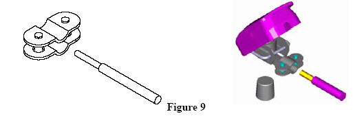
a) Using a 500mm (20”) length of the 2.5mm² 2-core power cable supplied, strip back the insulation each end and connect to clip-on battery terminals supplied. Fit a Red terminal to each end of the positive cable and a Blue terminal to each end of the negative cable. See Figure 9.
b) At the same time fit another cable long enough to reach the power monitor to one Red and one Blue terminals. See Figure 10.
Do not connect the batteries together or to the Power Monitor at this stage.
12. Fitting the Power Monitor
The Power Monitor should be located in a dry environment (indoors) as close as possible to the PC. It should always be installed on a vertical surface. When installed, ensure that the Power Monitor case is not in contact with any earthed metalwork since this may result in inaccurate readings.
a) Fix the Power Monitor to a vertical surface using suitable screws.
b) Fit the data cable to the 9 Way ‘D’ connector plug supplied. Strip back the insulation and make soldered connections. See Figure 11 and Table. Excess shielding should be folded back over the outer insulation and fitted under the strain relief clamp of the connector plug. Fit the cover. See Figure 12.

a) Remove the Power Monitor terminal block access cover to expose the internal terminal block. b) Thread the power leads from the Windcharger and solar panel through thecorresponding grommet in the underside of the Power Monitor and connect to the terminal block. c) Thread the battery lead through the grommet and connect to the Power Monitor terminal block. d) Connect the weather sensor 9 Way ‘D’ plug to the Power Monitor external socket. e) Connect the battery leads to the battery terminals. f) Connect the 25 Way cable provided to the Power Monitor and the Picolog 1012, Do not connect the USB cable from the Picolog 1012 to the PC until after the software is installed (see software installation section). For technical reasons use only the cables supplied, USB extension cable arrangements can be added under advice. g) Connect the load cable (if required) to the Power Monitor terminal block. Maximum load to be applied is 10A. Check rating of any appliance before connecting. h) Make final checks and replace the Power Monitor terminal block access cover.
14. Up and Running
Before erecting the tower make a final mechanical and electrical check of all
components. Avoid erection during strong wind conditions.
a) Uncover the solar panel and release the Windcharger blades.
b) Raise the tower taking all necessary health and safety precautions. We strongly recommend the use of hard hats when raising or lowering towers!
c) Check all guys, shackles etc. are fixed securely and permanently.
d) Check all electrical cables are securely fastened
.e)
Check the Power Monitor ammeters and voltmeter for readings, assuming necessary wind and light conditions are prevailing and the battery is connected.IN OPERATION
a) Power Monitor Displays
The four meters mounted on the front panel of the Power Monitor show instantaneous values of the Windcharger output current, the solar panel output current, the battery voltage and the battery load current (if a load is connected). The red LED illuminates when the battery voltage regulator is operating.
b) Power and Weather Monitoring/Logging Functions on Your PC
The basic features of the datalogging system are described in the “PicoLog Quick Start Guide” section of this manual. However we recommend that the user explore the full range of PicoLog features by referring to the HELP screens of the application.
c) Using the Battery as a Power Source
The batteries of your Green PowerEd system can be usefully employed to power 12V DC equipment some typical examples of which are listed below:-
12V Lamps
12V Pumps
12V Television
12V Motors, driving mechanical devices
12V Radio or other audio equipment
110/230V equipment can also be used via a suitable inverter provided the maximum current of 10A @ 12V is not exceeded. Note: The Power Monitor does NOT protect against excessive battery discharge. It is the responsibility of the user to disconnect as necessary. We recommend that the battery voltage is not allowed to drop lower than 11 Volts.
d) Maintenance
Your Green PowerEd system is essentially maintenance free. The outdoor components are designed to operate in that environment. The rotating components do not require lubrication.
The solar panel will be more effective if it is kept clean by wiping with a damp cloth, without detergent. The daylight sensor located in the top of the weather sensor assembly housing should be kept clean in the same manner. We recommend that the Windcharger be inspected on an annual basis as follows:-
• Tie up the Windcharger after slowing and stopping it from turning. • Lower the tower or gain safe access to the Windcharger • Check the blade screws are tight. • Check all other screws for tightness. • Check the yaw axis for free rotation. • Check the condition of the tower. • After raising the tower check guy wires for condition and tightness.IN OPERATION
a) Power Monitor Displays
The four meters mounted on the front panel of the Power Monitor show instantaneous values of the Windcharger output current, the solar panel output current, the battery voltage and the battery load current (if a load is connected). The red LED illuminates when the battery voltage regulator is operating.
b) Power and Weather Monitoring/Logging Functions on Your PC
The basic features of the datalogging system are described in the “PicoLog Quick Start Guide” section of this manual. However we recommend that the user explore the full range of PicoLog features by referring to the HELP screens of the application.
c) Using the Battery as a Power Source
The batteries of your Green PowerEd system can be usefully employed to power 12V DC equipment some typical examples of which are listed below:-
12V Lamps
12V Pumps
12V Television
12V Motors, driving mechanical devices
12V Radio or other audio equipment
110/230V equipment can also be used via a suitable inverter provided the maximum current of 10A @ 12V is not exceeded.
Note: The Power Monitor does NOT protect against excessive battery discharge. It is the responsibility of the user to disconnect as necessary. We recommend that the battery voltage is not allowed to drop lower than 11 Volts.
d) Maintenance
Your Green PowerEd system is essentially maintenance free. The outdoor components are designed to operate in that environment. The rotating components do not require lubrication. The solar panel will be more effective if it is kept clean by wiping with a damp cloth, without detergent. The daylight sensor located in the top of the weather sensor assembly housing should be kept clean in the same manner.
We recommend that the Windcharger be inspected on an annual basis as follows:-
• Tie up the Windcharger after slowing and stopping it from turning.
• Lower the tower or gain safe access to the Windcharger
• Check the blade screws are tight.
• Check all other screws for tightness.
• Check the yaw axis for free rotation.
• Check the condition of the tower.
• After raising the tower check guy wires for condition and tightness.
b) Is there sufficient daylight? The solar panel should operate in low light conditions such as overcast days although the power produced may be greatly reduced. Check for a reading on the Power Monitor ammeter.
c) Cover the solar panel, disconnect from the Power Monitor and connect to a multimeter set to DC volts. Remove the cover from the solar panel. In bright sunlight an open circuit voltage of 15 to 20V should be observed. If the reading is drastically reduced or no reading is observed refer to the manufacturer.
3. Batteries
The Power Monitor has to be energised (batteries connected) before the ammeters will display readings. Check that the battery voltmeter on the Power Monitor is showing a reading.
a) Check the battery voltage (when load is disconnected). Charge the batteries if this falls below 11 V before reconnecting the load.
b) If problems persist with batteries holding charge have them checked by your local garage or battery dealer. Replace if necessary. (Use only deep cycle type batteries)
4. Weather Sensors
If no readings are obtained from the weather sensors, check all electrical connections including those made to the ‘D’ plug. If the problem persists, refer to the manufacturer.
5. Power Monitor
If a problem occurs check all electrical connections to and from the Power Monitor. Check the 20A Fuse! If the fuse has blown the most likely cause is reverse polarity connection of one or more components, or using a higher load than specified. Under these conditions irreversible damage may have been caused to the Power Monitor - refer to the manufacturer.
SOFTWARE INSTALLATION & QUICK START GUIDE
The following section will enable you to set up the data logging system and begin logging straight away. For the success of the system we urge you to follow the strict sequence of software installation which should take only ten minutes or so.
1. Introduction
The Graduate Green Power Ed system incorporates a Pico technology Picolog 1012 analogue to digital converter plus PicoLog software in Windows format. Standard configuration files are included on a separate disk to provide correct configuration and calibration of all the parameters to be measured.
Please Note: The standard configuration files supplied with your Green Power Ed system correspond with the software version with which they were supplied. Updating the software may cause errors in the measured parameters. Please contact us for updates to configuration files if necessary.
Picolog software is a data acquisition tool providing facilities for recording data from all the measured parameters, providing displays in tabular and graphical formats with facilities for export to other software e.g. MS Excel. The following operating instructions give a quick guide to setting up, running and performing the basic operations for the Windows software. For further detailed instructions please refer to the software online help.PicoLog is provided in 2 forms; PicoLog Recorder & PicoLog Player, Recorder is for datalogging, Player is for viewing previously recorded data. Both Recorder and Player can be run simultaneously. Standard configuration files are supplied to provide correct calibration and display of all measured parameters.
2. Pico Software Installation & Set-up Important: Install the software before connecting the Picolog 1012 to the computer.
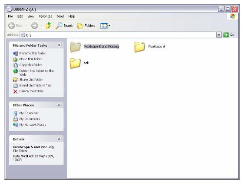
• Insert the software CD, the following window should appear: If it doesn’t, browse the CD using windows explorer.
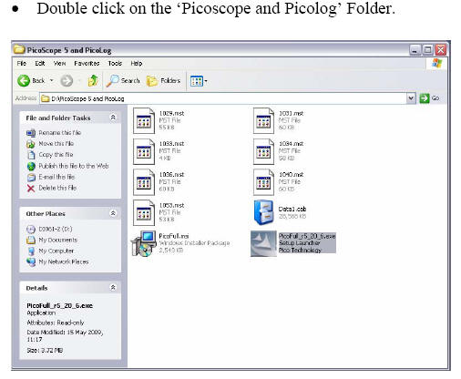
• Double click on the ‘Picofull_r*_**_*.exe’ icon. (r**_**_* refers to the software revision supplied). • Follow the on-screen prompts • Accept License Agreement. • Follow the on-screen prompts • Select Device ‘Picolog 1000 series’ from the drop down list
• Select Installation type ‘Typical’
• Follow on-screen prompts
• When installation is complete, close the folder window.
Leave the CD in the drive at this stage.
•
Connect the Picolog 1012 to a USB port on the PC using the leadprovided.
• The PC should display the ‘found new hardware’ window.
• Follow the prompts to install the drivers from the CD.
• A message will indicate that the Picolog 1012 is installed & ready to use.
• Remove the Software CD and insert Disk ‘Configuration Files’.
• Copy all Files from the CD to C:\Program Files\Pico technology\Pico Full.
• If prompted that a file already exists and are asked whether or not you wish to overwrite, select ‘overwrite all’.
• The Configuration files disk should be removed and both kept safe.
• Connect the cable provided between the Power monitor & the Picolog 1012.
3. PicoLog Quick Start Guide
This section gives a brief guide to get you up & running quickly with the Picolog software, for further help once familiar with the software please see the online help.• Start PicoLog Software. Double click the PicoLog Icon on the desktop or select Start, Programs, Pico Technology, Picolog Recorder.
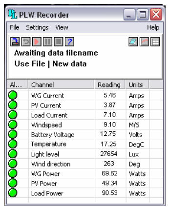
• The PLW Recorder window should appear showing a list of the basic preconfigured parameters. The figures in the display should be seen to change corresponding with the signal being measured.
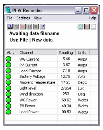
Note: If the column widths are too narrow to display their contents the width can be adjusted using the cursor.
Note: The monitor display following installation as above, does not show a windspeed reading, this is due to a peculiarity in the software which requires it to be configured on the PC on which it is to be displayed. The following procedure will add the windspeed to the display.
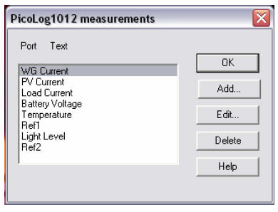
• Click the ‘Add’ button
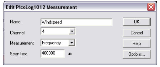
• Complete the boxes as shown above
• Click the ‘Options’ button. When prompted to save changes to continue, select ‘yes’.
• Complete the boxes as shown above
• Click the ‘Scaling Button
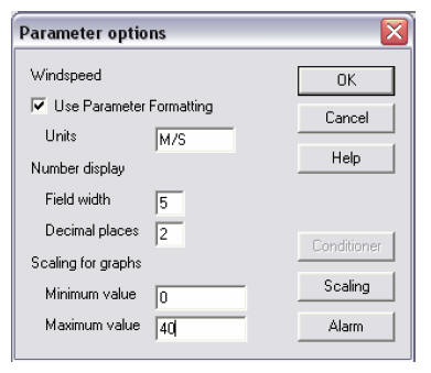
• Complete the boxes as shown above
• Click the ‘Scaling Button
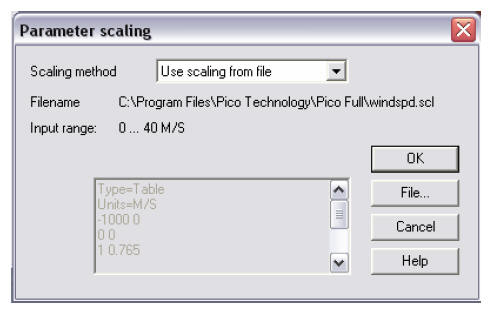
• Select the scaling method from the drop down list as ‘Use scaling from file’
• Click the ‘File button’
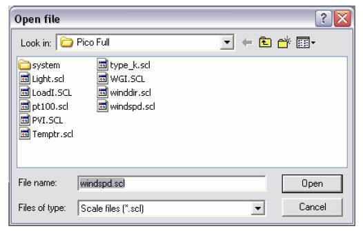
• Select ‘windspd.scl’ and click ‘Open’
• Click ‘OK’ on all windows until the monitor is displayed which will now have windspeed added to the list.
• Click on ‘File’, ‘Save As’
• From the ‘Save as type’ drop down list, select ‘Settings files (*.pls)’ & select the ‘RECORDER.PLS’ file

From the ‘Save as type’ drop down list, select ‘Settings files (*.pls)’ & select the ‘RECORDER.PLS’ file
• Click the ‘Save’ button & when prompted to overwrite the existing file, answer ‘Yes’
• Exit the PicoLog Recorder software, wait a few seconds & then restart PicoLog. The windspeed reading has now been configured & will be displayed in the list.
The software is now configured & ready to use.
Change the Monitor displayed parameters
The user can select what is displayed on the monitor view, eg you may want to only display inputs associated with the Wind generator.
Note: The default configuration will display ‘Wind direction’, if you do not have the optional wind direction vane this display should be turned off by following the procedure below:
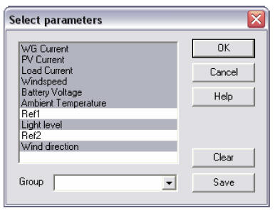
• Select ‘Settings’, ‘Monitor’.
• Highlight the parameters you wish to display, remove the highlight from items you wish not to be displayed. Clicking on an item will toggle its highlight.
• If desired, group names can be allocated to a selection of parameters & saved for re-call at a later stage.
• Select ‘OK’ to update the monitor display with the new selections.
Set-up Datalogging
The system has been provided with convenient default settings to get the user up and running as quickly as possible.
The default settings will log all signals and store the 5 minute average for each. Each data file consists of a 24hr period and the data file name will automatically increment by 1 at the end of each 24hrs.
Select File, New Data or click the icon below the menu bar.
Type in the required filename. It is convenient to use the current date as the filename with the format YY,MMM,DD, e.g. 03JUL01 representing 1
st July 2003.This method provides filenames representing each day the file was created, since as each file is completed the file name will increment by 1. At the beginning of each month it will be necessary to correct the Filename since it is not recognised as an actual date. Eg after the 31
st of the month the file will change to 03JUL32. which will need to be manually changed to 03AUG01.Please Note: The default settings provided (e.g. sample interval, total samples etc) can be changed by the user to suit the test being performed, it is important however that the parameter scalings are not changed since these provide correct calibration of the sensors.
• Highlight the parameters you wish to display, remove the highlight from items you wish not to be displayed. Clicking on an item will toggle its highlight.
• If desired, group names can be allocated to a selection of parameters & saved for re-call at a later stage.
• Select ‘OK’ to update the monitor display with the new selections.
Set-up Datalogging
The system has been provided with convenient default settings to get the user up and running as quickly as possible.
The default settings will log all signals and store the 5 minute average for each. Each data file consists of a 24hr period and the data file name will automatically increment by 1 at the end of each 24hrs.Select File, New Data or click the icon below the menu bar. Type in the required filename. It is convenient to use the current date as the filename with the format YY,MMM,DD, e.g. 03JUL01 representing 1
st July 2003. This method provides filenames representing each day the file was created, since as each file is completed the file name will increment by 1. At the beginning of each month it will be necessary to correct the Filename since it is not recognised as an actual date. Eg after the 31st of the month the file will change to 03JUL32. which will need to be manually changed to 03AUG01.Please Note: The default settings provided (e.g. sample interval, total samples etc) can be changed by the user to suit the test being performed, it is important however that the parameter scalings are not changed since these provide correct calibration of the sensors.
Change Recording Parameters
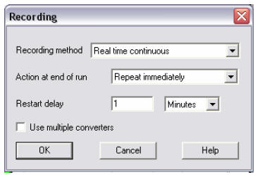
• Select Settings, Recording
•
Leave the recording method as ‘ Real Time Continuous’.The default setting for Action is ‘Repeat immediately’. At the end of the current datalogging run, the file name will automatically increment by 1 and a new run will start. If it is required to perform only a single run then the action can be changed to ‘Stop’.
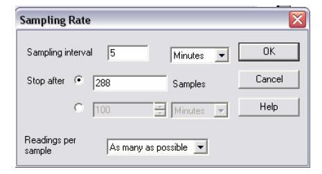
The sample interval and maximum number of samples per run can be changed as desired. The default is 5 minute sample interval and 288 samples, which produces a file covering a 24hr period.
The readings per sample are set as a default to ‘As many as possible’ where the PC will take as many readings as possible during the sampling interval and record the average of these. This is normally the most accurate method when using long sample intervals.
Start Datalogging
• Click the Start Recording Icon below the menu bar. The display in the Recorder window will change to say ‘Recording’ and will show the current No of samples recorded. Recording can be stopped at any time by clicking the Stop Recording Icon .
Adding or Editing notes
.Click the Notes Icon , a window will display the current notes for editing which will be added to the current data file and displayed on the graphs.
Displaying Graphs
Select View, Graphs or click the graphs icon , the standard Y vs Time graph will display.
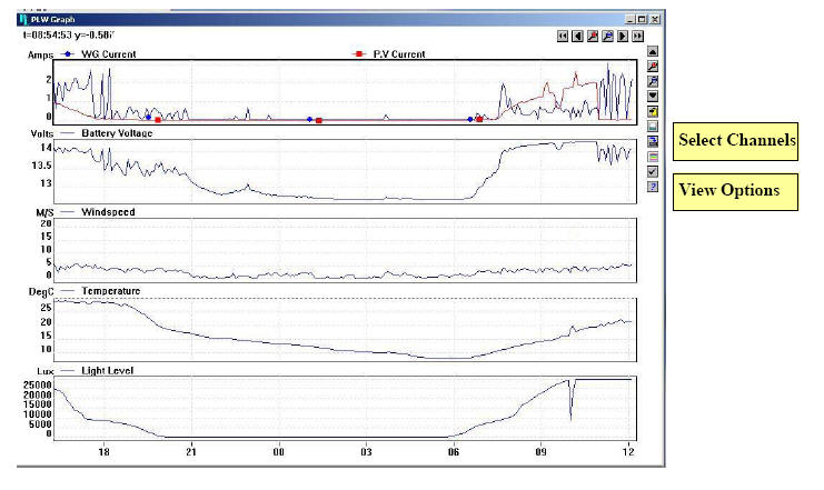
Move the cursor over the icons at the top and right of the graph, the icon description will appear. Channels displayed may be selected by clicking the Select Channels Icon
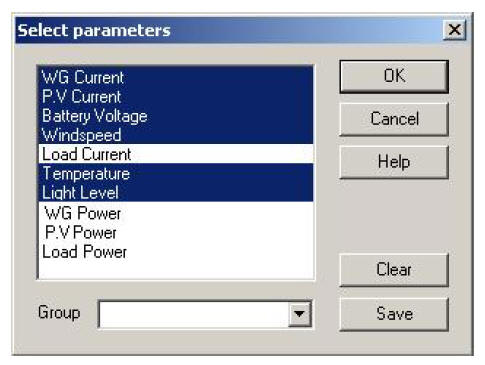
The required channels can be selected or de-selected; settings can be saved or recalled as groups with user definable names. Click OK, the current selection of channels will be displayed on the graph. Graphs may be displayed or changed while logging is in progress, graph data will be displayed in real time as data is recorded.