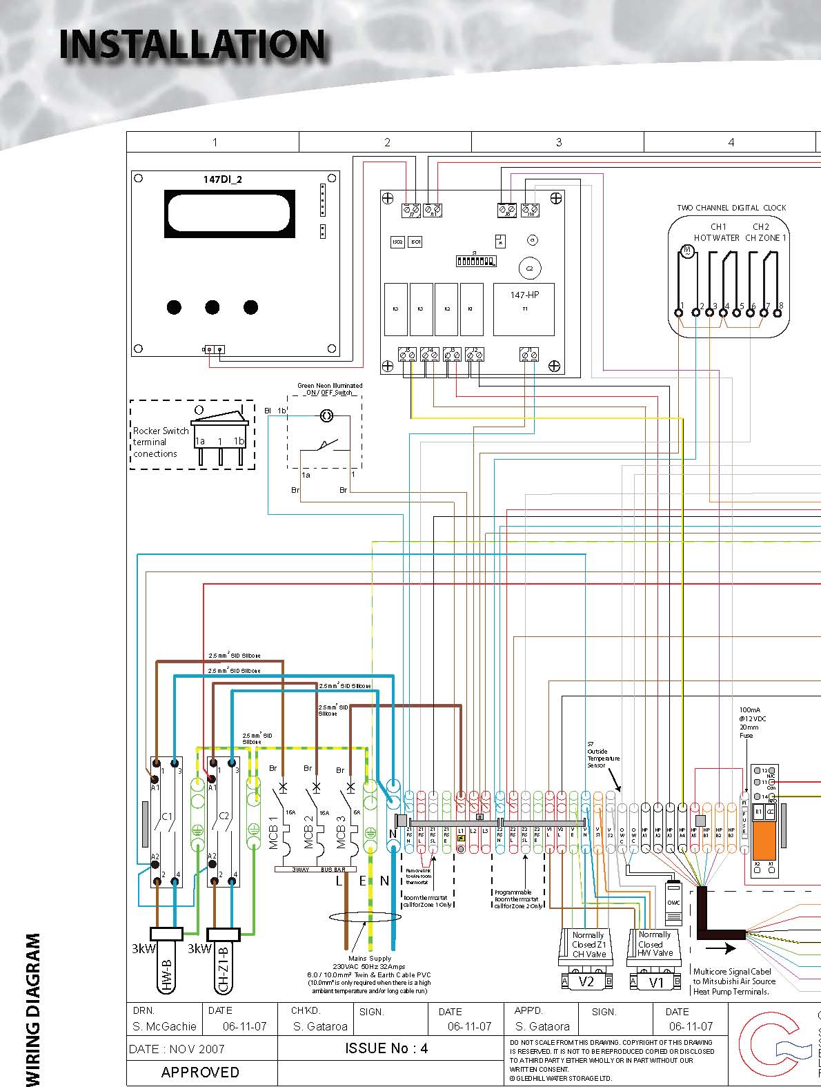
necessary wiring are shown opposite and on the electrical schematic drawing (see pages 26 and 27).
All the terminals are suitably labelled on the appliance.
manual.
Run the external wiring through the service slot provided in the base of the appliance. Make the connections as shown opposite on
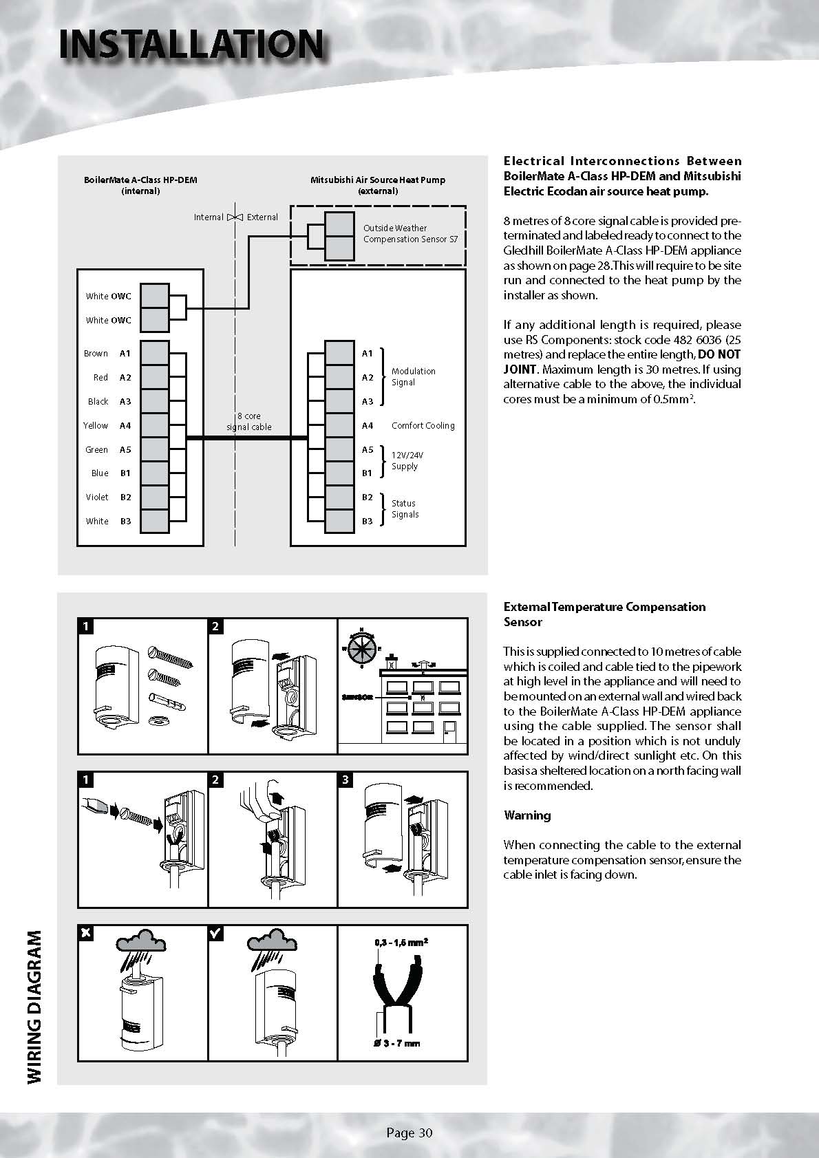
The room thermostat should be wired as shown opposite. The link in Z1RSL to Z1RSSL must be
removed when the room thermostat is fitted.
The time and temperature controls for CH zone 2 should be wired as necessary into the Z2 terminals provided.
When frost protection is required for the whole house set channel 2 of the clock to constant during the time required and adjust the room thermostat to a suitable setting.
| System |
| Check and adjust as necessary the hot water system expansion vessel(s) air pressure | |
| to 1.5 bar. | If it is proposed to ‘powerflush’ the heating |
| system always check and comply fully with |
| Check that any drain valves are closed then open the incoming stop valve and fill the | t he m a n u f a c turer s in s t r u c t i o n s fo r t he |
| domestic mains cold and hot water systems in the normal way ensuring there is no | powerflushing equipment being used. |
| air trapped in the system. | |
| It is recommended that the heat pump and the |
| Check and adjust as necessary the primary heating system expansion vessel to the | BoilerMate A-Class HP appliance is bypassed |
| figure specified (normally 1.0 bar). | during powerflushing of the primary/heating |
| system. |
| Note: The expansion vessel pressures should be checked before the systems are | |
| filled. | If in any doubt please consult our Technical |
| Helpline. |
| Fill the primary heating system with potable water through the filling loop provided | |
| to the pressure required (normally 1.0 bar). | Cleansing the Hot/Cold Water System |
| During filling vent air as necessary from the high points of the system including | Fully flush and, when necessary, chlorinate the |
| the manual air vents provided on the appliance and on the feed to the expansion | hot and cold water system in accordance with |
| vessel. | the recommendations in the Model Water |
| Byelaws and BS 6700. |
| Check the whole of the primary heating and domestic hot and cold distribution | |
| systems for leaks. | Remove and clean the strainer element in the |
| combination inlet valve, then replace it and re- |
| It is essential that all systems functions properly for optimum performance. | fill the systems. |
| To achieve this,the primary system should be commissioned in accordance with good practice | Once the systems have been refilled manually |
| and generally in accordance with the requirements of BS 6798, BS 5449 and BS 7593. | open the relief valves one by one and check |
| that water is discharged and runs freely through |
| When using either cleansing or corrosion inhibitor chemical, the manufacturers | the tundish and out at the discharge point. The |
| instructions must be followed. | pipework should accept full bore discharge |
| without overflowing at the tundish, and the |
| Cleansing the Primary System | valve should seat satisfactorily. |
| It is very important to ensure that the Primary system is cleaned using a suitable | On completion, check the pressure in the |
| cleansing agent such as Fernox F3 to ensure that any flux residues/installation | primary system is correct and disconnect the |
| debris are removed. | manual filling loop. |
| The cleaning should be carried out fully in accordance with the manufacturers | |
| instructions. To allow thorough flushing, full bore drain valves should be provided. | |
| Primary Water System Treatment | |
| Although the BoilerMate A-Class HP-DEM has no special water treatment requirements, | |
| the radiators and other parts of the circuit will require the application of a scale and | |
| corrosion inhibitor.The heat pump and external connecting pipework will also require | |
| protection against freezing. For this reason a combined anti freeze and inhibitor | |
| product such as Fernox Alphi 11 must be used. | |
| The volumes/concentration should be calculated in accordance with the manufacturers | |
| instructions allowing 10 litres for the volume for the primary pipework/coil in the | |
| BoilerMate A-Class HP appliance. | |
| We consider that in typical radiator systems, the total water volume will not exceed | |
| 80 litres. On this basis, 20 litres of Alphi-11 will provide at least the 25% concentration | |
| recommended by the manufacturer as the minimum.However,because of the volumes | |
| experienced in underfloor system, the system volume for these types of systems will | |
| need to be calculated. | |
| The Fernox Boiler Buddy supplied separately with the appliance package should be | |
| installed internally on the heat pump return as near as practical to the heat pump | |
| - see page 48 for further details. | |
Turn on the BoilerMate A-Class HP-DEM and check that the sensors and all controls operate correctly as well as any motorised valves. Check that no water discharges from either the expansion valve or temperature and pressure-relief valve during the heating cycle.
Check the appliance, the heating system and hot water system for leaks when hot.
Check that the correct outlet pressure is being maintained on the domestic water systems by the pressure reducing valve by checking the pressure at a hot tap or in the tapping provided on the combination inlet valve.
Check the correct flow is being achieved at each tap and the implications of opening more than one tap at the same time. If necessary fit flow regulators to each tap if these have not already been provided.
The heating systems and pumps should be set and balanced in the normal way to provide the temperature differential in line with the system design parameters chosen.
The primary system and pump to the heat pump should normally be set to speed 3.
If an automatic bypass valve is provided on the primary/heating circuit, check/adjust this as necessary to suit the particular installation requirements.
The room thermostat/clock or programmable room thermostat controls the heating and hot water systems and should be set to suit the householders requirements using the instructions provided with the controls.
These Instructions should be replaced along with the component manufacturers instructions in the pocket provided on the appliance and the front panel refitted.
If the system is not likely to be used continuously after testing/commissioning it should be isolated from the water and electricity supply and either drained down or have the pressure removed from both the heating and water systems.
DO check the incoming mains water pressure and flow rate are adequate. (The preferred range of mains pressure is 2.5-3.5 bar).
1.5 bar.
DO check that all plumbing and electrical connections are in accordance with the labelling on the unvented storage appliance.
DO insulate any exposed pipework in the BoilerMate A-Class HP-DEM cupboard and insulate/waterproof the external pipework to the heat pump.
DO check the pump settings give the correct temperature difference across the flow and return in the primary/heating circuits.
DO ensure that the bypass valve is set correctly.
DON’T operate any immersion heaters until the appliance/systems are fully filled, vented and commissioned.
DON’T place any clothing or other combustible materials against or on top of this appliance.
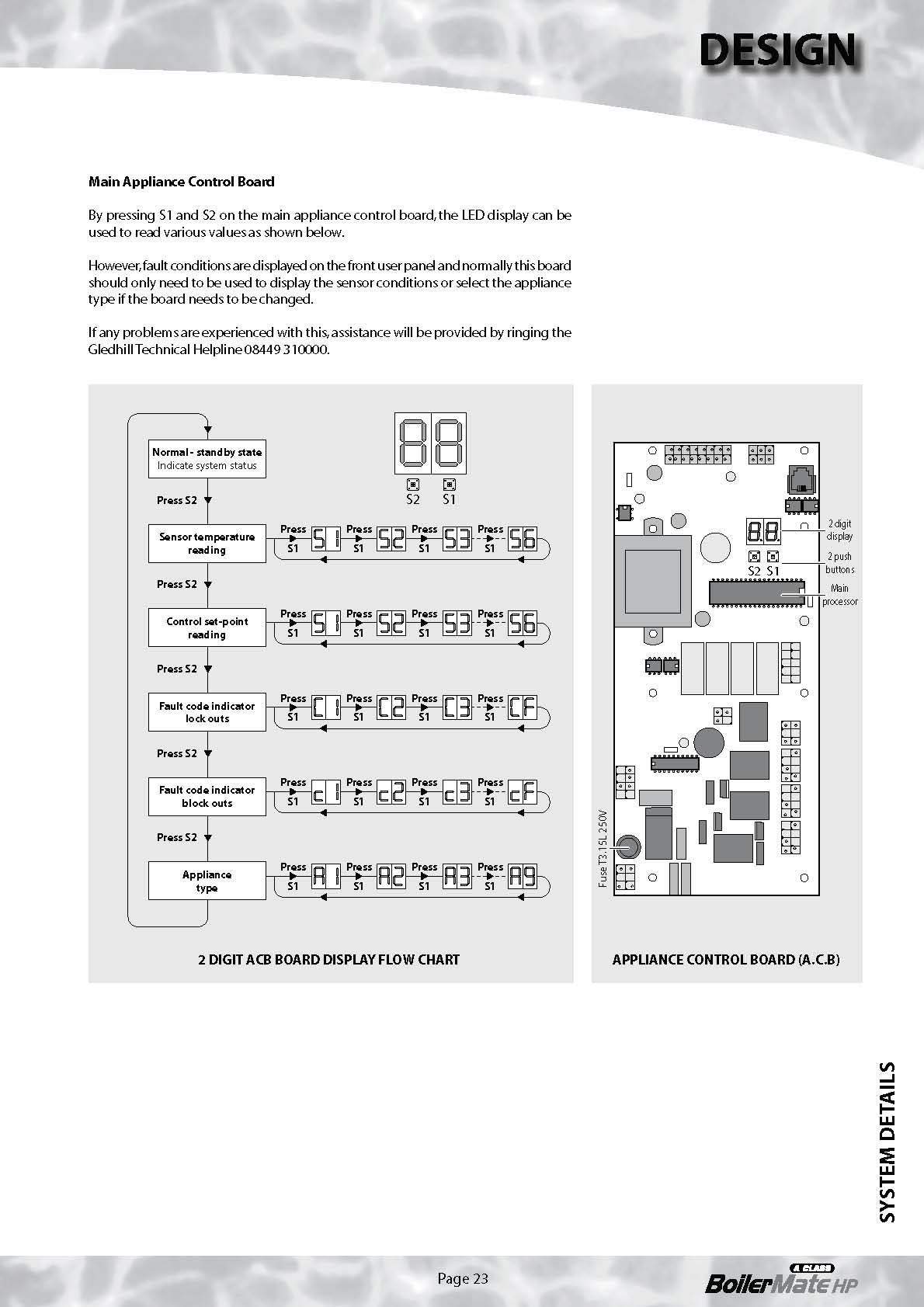
DO ensure that the discharge pipework from the relief valves is/are installed to a fall and are of the correct size so that water does not overflow when a relief valve operates.
DO ensure the discharge point is safe and in accordance with the G3 Building Regulations.
DO check and ensure the air pressure side of the heating expansion vessel is set at 1.0 bar (or as specified).
DO check that the primary system pressure does not exceed 2 bar when the whole of the primary/heating system are up to temperature.
DO ensure that all systems are thoroughly flushed and cleaned and that a Fernox Boiler Buddy is fitted internally on the return as near as possible to the heat pump.
DO ensure that the inhibitor used is a combined product incorporating antifreeze and that sufficient has been added to provide at least the minimum concentration level recommended by the manufacturer.

Page 32

Servicing/Maintenance
The Registered Installer is responsible for the safe installation and operation of the system. He must also make his customer aware that periodic checks of the equipment are required by the Building Regulations and essential for safety.
Maintenance and inspection periods will vary for many reasons. Gledhill Water Storage Ltd recommend a maximum of 12 months between inspections. Experience of local water conditions may indicate that more frequent inspection is desirable, eg. when water is particularly hard and scale-forming or where the water supply contains a high proportion of solids, eg. sand. For Maintenance see the table below:
| 1 | With the water supply turned off, remove the screen from the strainer in the combination inlet valve and clean off any detritus (dirt). |
| 2 | With the water supply turned off and the hot taps open, check the expansion vessel charge pressure and top up as necessary (1.5bar). |
| 3 | With the water supply turned on, open the temperature relief valve and then expansion valve to check for unrestricted discharge into tundish. Check valves for freedom of movement and confirm that the water stops and both valves reseat correctly. Check at a full bore discharge from either valve that there is no back up or discharges over the tundish. |
| Check that the correct outlet pressure is being maintained by the pressure |
| 4 | reducing valve by recording the presure at a terminal fitting or the tapping |
| provided on the combination inlet valve. |
| 5 | Clean flow regulators (or restrictor/aerators) on each terminal fitting tap/ shower as applicable. Check for correct flow rate at terminal fittings. |
| 6 | Visually inspect, checking for the presence of supplementary bonding and that it is being maintained. |
| 7 | Check correct rating and type of fuse is fitted on the electrical supply. |
| 8 | Check for the correct operation and temperature setting of the thermostats. |
| 9 | Check the operation of the motorised valves. |
| 10 | Check the operation of ‘Switch’. |
| 11 | If necessary descale the heat exchangers immersion/heaters in hard water |
| areas. |
The Registered Installer is responsible for the safe installation and operation of the system. He must also make his customer aware that periodic checks of the equipment are required by the Building Regulations and essential for safety.
Maintenance and inspection periods will vary for many reasons. Gledhill Water Storage Ltd recommend a maximum of 12 months between inspections. Experience of local water conditions may indicate that more frequent inspection is desirable, eg. when water is particularly hard and scale-forming or where the water supply contains a high proportion of solids, eg. sand. For Maintenance see the table above:
The above service/maintenance recommendations relate to the BoilerMate A-Class HP-DEM appliance only. Any service of the heat pump/heating system should include checks on the water pressure in the primary/heating systems and the air pressure in the primary expansion vessel with the system pressure removed.
Service of the heat pump is covered elsewhere in this manual. It is recommended that the Fernox Boiler Buddy is checked and cleaned at the same time as the BoilerMate A-Class HP-DEM appliance is serviced. The concentration of the inhibitor should also be checked and if necessary topped up with Alphi-11 to at least the minimum 25% level recommended by the manufacturer.
Changing Components
If it is necessary at any time to drain the storage vessel either for system modifications or to replace a component the appliance must be drained in the following way.
Before draining open all hot taps in the system then hold open the pressure and temperature relief valve until water stops discharging into the tundish.
Open the drain cock and immediately hold open the P & T relief valve again. This must be held open until the cylinder is completely drained.
When the unit is re-filled ensure the drain valve does not leak.
The KIWA Approvals for the BoilerMate A-Class HP-DEM appliance are conditional on the specific manufacturer/type of components fitted and any replacements must be purchased direct from Gledhill to ensure compatibility/ continued safe operation.
Free of charge replacements for any faulty components are available from Gledhill during the in-warranty period (normally 12 months).
However, if any component is damaged during installation a new replacement must be ordered and paid for.
After this, spares should be obtained direct from Gledhill using the ‘Speed Spares’ service, or through any of the larger plumbers merchants/ specialist heating spares suppliers.
Help and advice is also available from the Technical Helpline on 08449 310000.
However, all components are readily accessible and can be changed quickly and easily by the installer using common plumbing practice.
If it is necessary to replace any of the pumps fitted to the appliance the pump head (motor pack)only should be removed as recommended by Grundfos. It is important when a pump has been replaced to ensure that any air is adequately vented.
ANNUAL SERVICE/CHANGING COMPONENTS

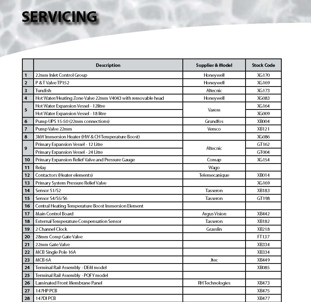
SHORT PARTS LIST


| In accordance with the Benchmark Guidance Notes in hard water areas, above 200ppm | If cold water is discharging from the expansion |
| (mg/l) it is recommended that an in-line scale reduction device is fitted. Reducing the | relief valve drop the system pressure and check |
| temperature of the stored water will reduce the rate at which scale forms but must not | the air pressure in the expansion vessel is 1.5 |
| be reduced to less than 60°C. If the recovery rate is badly affected, this is an indication | bar. |
| that scaling may have occurred. In this event, follow the procedures as recommended | |
| by a reputable Water Treatment Company. | If the fault continues and the problem cannot |
| be stopped by operating the easing control a |
| General | few times then either the Pressure Reducing |
| Valve or the Relief Valve may be at fault. If the |
| All work must be carried out by a suitably qualified/competent person. | cold water pressure is too high, this would |
| suggest that the Pressure Reducing Valve is at |
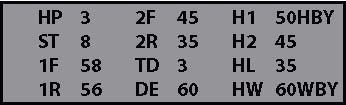
| The display window on the front of the appliance has the facility to indicate fault | fault and the Gledhill approved replacement |
| conditions as a reference code and as a written description ie: Fault 10/sensor fault. | should be fitted. If the pressure is correct then |
| This should be interrogated before any work is undertaken. | the Relief Valve/cartridge will require replacing |
| with a Gledhill approved component. |
| The main control board also has an LED panel which can also be used to show various | |
| set points/fault codes but it is normally recommended that on this appliance, the front | If there is an overheat fault and very hot water is |
| panel is used when fault finding. | being discharged, turn off the heat source, but |
| not the water supply. When the system is cool, |
| No/Reduced flow of hot water at the taps | check the control and overheat thermostats |
| and energy cut-outs in the immersion heater |
| Check that the mains water supply is turned ON. Check the line strainer in the | and replace the faulty component with a unit |
| combination inlet valve is not blocked. Check that the combination valve has been | supplied by Gledhill and check that it works |
| fitted so that water is flowing in the correct direction. | correctly before returning the system to full |
| operation. |
| If the water at the tap is cold | |
| Ensure that the heat pump has been switched ON and is working correctly. Check that | |
| there are no air locks in the primary system. ISOLATE THE UNIT AT THE MAINS ELECTRIC | |
| SUPPLIES AND THEN CHECK THE FOLLOWING:- | |
| i) The control thermostat | |
| ii) The overheat thermostat,which can be reset by unscrewing the cover and pushing | |
| the red button. | |
| Note: If the overheat thermostat has been activated, we recommend that the | |
| control/overheat stat is replaced. | |
| iii) The motorised valve | |
| iv) Check that the heat is being produced by the heat pump and the pump is running. | |
| If the heat pump is running check/replace the 100MA (F1) fuse provided on the | |
| BoilerMate A-Class HP-DEM terminal strip to protect the main control board from | |
| a fault on the heat pump. | |
| If for any reason heat is not being supplied to the appliance heating and/or hot water | |
| can be obtained by operating the ‘Switch’ controls on the front of the appliance. | |
| Any Energy Cut-out Must Never Be By-passed Under Any Circumstances. | |
| If the unit is still getting hot , ensure that the immersion heater is isolated from the | |
| mains before re-setting the energy cut-out. If the immersion heater(s) need replacing | |
| this should be done with the unit supplied from Gledhill Water Storage Ltd. Same day | |
| despatch to approved installers can be arranged by telephoning 08449 310000. | |
FAULT FINDING


Ecodan Air to Water Heat Pump PUHZ-W90VHA
INSTALLATION MANUAL
FOR INSTALLER
INSTALLATION MANUAL
For safe and correct use, read this manual thoroughly before installing the unit.
Available from www.gledhill.net/downloads
Mitsubishi Parts Catalogue - PUHZ-W90VHA Mitsubishi Service Manual - PUHZ-W90VHA


Installation requirement checklist for Mitsubishi Electric Ecodan Heat Pump Boiler
The following items are considered essential to ensure satisfactory functioning of the Mitsubishi Electric Ecodan Heat Pump Boiler. Omission of any of these willresultin unsatisfactory performance, some of which willcompromise the longevity, energy efficiency, and running costs of the system.
1. Unit Location
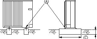
The location of the unit will need to take into consideration local planning regulations. The positioning shall allow for an unobstructed air flow. The unit should be installed upright and on a level base. Dependant upon the unit location there may be a requirement for condensate removal by using either drain sockets or a drain pan. For clearance details please refer to the later section of this installation manual.
2. Pipework Insulation
All external pipe work shall be insulated to ensure minimal thermal heat loss and also weather protection. Mineral wool insulation (internal diameter 22mm, thermal conductivity 0.04W/m.K) shall be used along with Plysolene sheeting (PIB) to wrap around for weather protection.
3. Anti Vibration Mounts
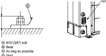
The Heat Pump Boiler unit must be securely fixed using 4 X M10 boltsinto a firm foundationin allcases. Anti-vibration mounts should be used when the Heat Pump Boiler is mounted on the ground or on wall brackets.
4. Anti Vibration Connections (flexible hose, supplied loose)
All installer supplied pipe work must be connected to the heat pump boiler by using QTY2 600mm 1” bore steel braided rubber flexible hose, one for flow and one for return which are supplied with the unit. Pipe work between the unit and the Hot water tank shall be minimum 22mm. Provision shall be taken to avoid this pipe work freezing during winter months.
5. System Water Contamination
The heat exchanger in the heat pump must be protected from particulate contaminates in the water circuit. When retrofitting within an existing heating system sufficient provision must be taken to clean the existing systems to avoid contaminates blocking the water circuit within the Heat Pump.
The existing radiator circuit MUST be chemically cleaned and thoroughly flushed by a competent person before installation in all cases.
A high gradeinline magnetic particulate filter such as the Fernox Boiler Buddy or the Spirovent SV3-025-T must beinstalled internally in the boiler return, as near as possible to the heat pump. The Fernox Boiler Buddy is supplied as part of this package and should be installed fully in accordance with the details provided at the back of this installation manual.
When the system is clean, it should be protected by the addition of a combined inhibitor/antifreeze such as Alphi-11 installed fully in accordance with the manufacturers recommendations.
To protect the heat pump from damage and to ensure that the product is covered by the warranty the system water should have the following maximum levels:
Calcium: 100mg/l Chlorine: 200mg/l Iron / Manganese: 0.5mg/l
INSTALLATION MANUAL


Contents
- Safety precautions . . . . . . . . . . . . . . . . . . . . . . . . . . . . . . . . . . . . . . . . . . . . . . 2 5. Water piping work . . . . . . . . . . . . . . . . . . . . . . . . . . . . . . . . . . . . . . . . . . . . . . 5
- Installation location . . . . . . . . . . . . . . . . . . . . . . . . . . . . . . . . . . . . . . . . . . . . . 36. Electrical work . . . . . . . . . . . . . . . . . . . . . . . . . . . . . . . . . . . . . . . . . . . . . . . . . 5
- Installation procedures . . . . . . . . . . . . . . . . . . . . . . . . . . . . . . . . . . . . . . . . . . . 4 7. Test run . . . . . . . . . . . . . . . . . . . . . . . . . . . . . . . . . . . . . . . . . . . . . . . . . . . . . . 6
- Drainage piping work . . . . . . . . . . . . . . . . . . . . . . . . . . . . . . . . . . . . . . . . . . . . 5
1. Safety precautions
 After installation, perform the test run to ensure normal operation. Then explain your customer the “Safety Precautions,” use, and maintenance of the unit based on the information in the Operation Manual. Both the Installation Manual and the Operation Manual must be given to the user. These manuals must always be kept
 Warning: by the actual users.Precautions that must be observed to prevent injuries or death.

 : Indicates a part which must be grounded.
Caution: Precautions that must be observed to prevent damages to the unit.
 Warning:
Carefully read the labels attached to the unit.
Warning:
Carefully read the labels attached to the unit.
 Warning:
- The unit must not be installed by the user. Ask an installer or an autho-• When installing or moving the air to water heat pump, make sure to use the rized technician to install the unit. If the unit is installed improperly, water specified refrigerant (R410A) to charge the refrigerant lines. Do not either leakage, electric shock, or fire may be caused. mix it with any other refrigerant or allow air to remain within the pipes. Air
- The unit must be installed according to the instructions in order to minimize the risk of damages by earthquakes, typhoons, or strong winds. Improperly installed unit may fall down and cause damages or injuries.
enclosed in the pipes can cause pressure peaks resulting in a rupture and other hazards.
• Make sure to use accessories authorized by Mitsubishi Electric and ask
• The unit must be securely installed on a structure that can sustain its weight. If the unit is mounted on an unstable structure, it may fall down and cause damages or injuries.
an installer or an authorized technician to install them. If accessories are improperly installed, it may cause water leakage, electric shock, or fire.
• Do not remodel the unit. Consult an installer for repairs. If alterations or
• If the air to water heat pump is installed in an enclosed area, measures must be taken to prevent the refrigerant concentration in the room in the event of refrigerant leakage. Consult an installer regarding the appropriate measures. Should the refrigerant leak and cause the concentration oxygen in the room may lack.
repairs are not performed correctly, it may cause water leakage, electric shock, or fire.
• The user should never attempt to repair the unit or transfer it to another location. If the unit is installed improperly, it may cause water leakage, electric shock, or fire. If the air to water heat pump needs to be repaired or
- Ventilate the room if refrigerant leaks during operation. If refrigerant comes moved, ask an installer or an authorized technician. into contact with a flame, poisonous gases will be released. • After installation has been completed, make sure that refrigerant does not
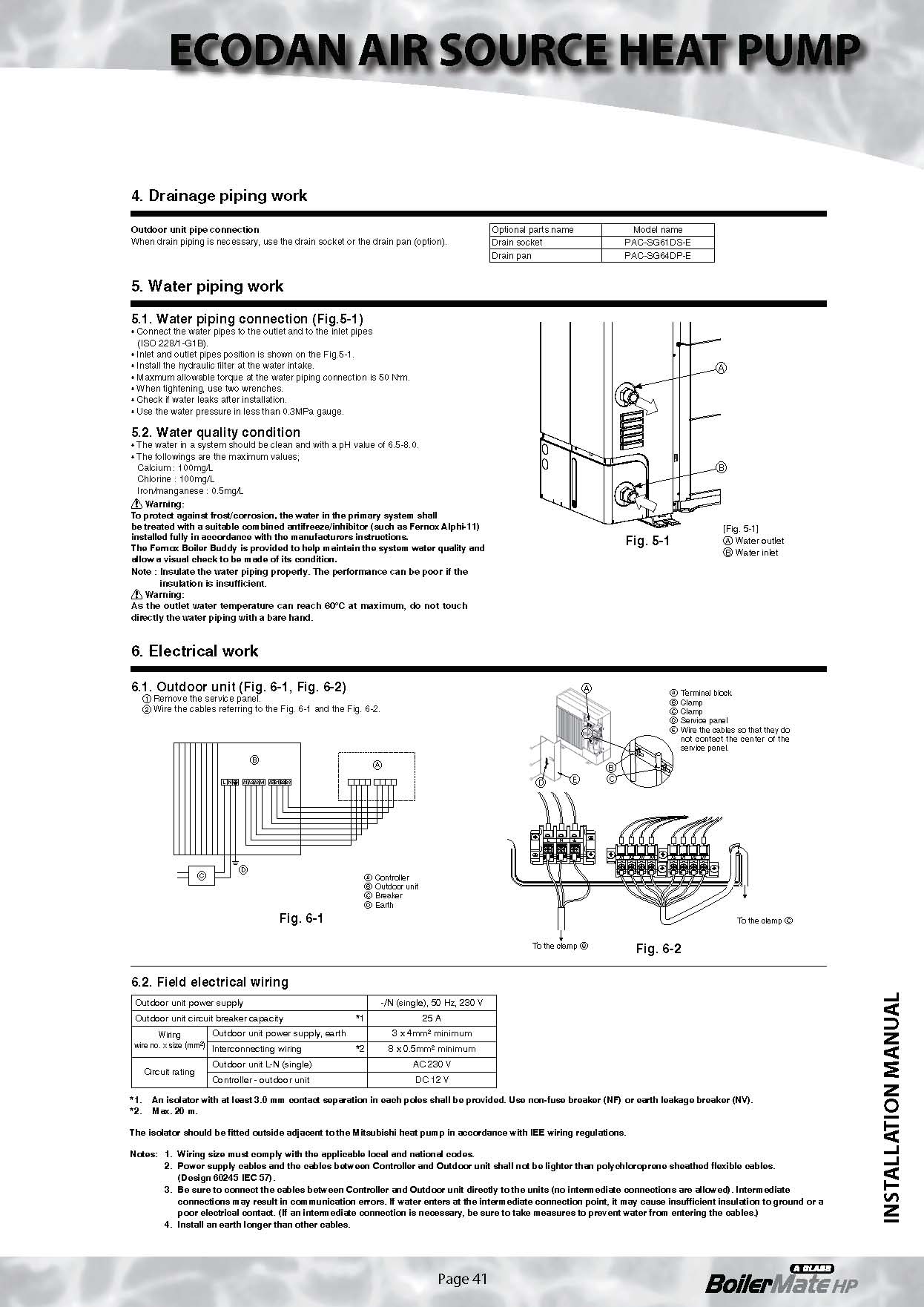
- All electric work must be performed by a qualified technician according to local regulations and the instructions given in this manual. The units must be powered by dedicated power lines and the correct voltage and circuit breakers must be used. Power lines with insufficient capacity or incorrect electrical work may result in electric shock or fire.
leak. If refrigerant leaks into the room and comes into contact with the flame of a heater or portable cooking range, poisonous gases will be released.
• Use clean enough water which meets water quality standards. The deterioration of water quality may result in the system breakdown or the water
- Only the specified cables can be used for wiring. Connections must be leakage. made securely without tension on the terminals. If cables are connected or • Never use anything other than water as a medium. It may cause a fire or an installed improperly, It may result in overheating or fire. explosion.
- Terminal block cover panel of the outdoor unit must be firmly fixed. If the • Do not use heated or cooled water that is produced by the air to water cover panel is mounted improperly, dust and moisture may enter the unit, heat pump directly for drinking or cooking. There is a risk to damage your and it may cause electric shock or fire. health. There is also a risk that installing the water heat exchanger may
corrode if the necessary water quality for the air to water heat pump system cannot be maintained. If you wish to use the heated or cooled water from the heat pump for these purposes, take measure such as to the second heat exchanger within the water piping system.
INSTALLATION MANUAL
1.1. Before installation
 Caution:
• Do not use the unit in an unusual environment. If the air to water heat pump is installed exposed to steam, volatile oil (including machine oil), or sulfuric gas, or exposed to briny air, or covered with snow, the performance can be significantly reduced and the internal parts can be damaged.
• When installing the unit in a hospital or in a building where communication equipments are installed, you may need to take measures to noise and electronic interference. Inverters, home appliances, high-frequency medical equipment, and radio communications equipment can cause the air to
- Do not install the unit where combustible gases may leak, be produced, flow, or accumulate. If combustible gas accumulates around the unit, it may cause fire or explosion.
water heat pump to malfunction or to breakdown. At the same time, the noise and electronic interference from the air to water heat pump unit may disturb the proper operation of medical equipment, and communications
The outdoor unit produces condensate during the heating operation. Make equipment. sure to provide drainage around the outdoor unit if such condensate is likely to cause damage.
1.2. Before installation (relocation)
 Caution:
• Be fully careful when moving the units. The unit must be carried by at least 2 people, as it weighs 20 kg or more. Do not hold the packaging bands. Wear protective gloves to unpack and to move it, in order to avoid your hands be injured by fins or other parts.
• The base of the outdoor unit must be periodically checked to ensure not being loose, cracked or damaged. If such defects are left untreated, the unit may fall down and cause damage or injuries. • Do not wash the air to water heat pump unit. You may receive an electric
• Be sure to safely dispose of the packaging materials. Packaging materials, shock. such as nails and other metal or wooden parts may cause injuries.


1. Safety precautions
• Make sure to ground the unit. Do not connect the ground wire to gas or
 Caution: water pipes, lighting rods, or telephone grounding lines. If the unit is not
1.3. Before electric work
- Be sure to install a circuit breaker. If it is not installed, there may be a risk properly grounded, there may be a risk to get an electric shock. to get an electric shock. • Make sure to use circuit breakers (ground fault interrupter, isolating switch
- For the power lines, use standard cables of sufficient capacity. Otherwise, (+B fuse), and molded case circuit breaker) with the specified capacity. If it may cause a short circuit, overheating, or fire. the circuit breaker capacity is larger than the specified capacity, break
- When installing the power lines, do not apply tension to the cables. The down or fire may result. cables may be cut or overheated resulting in a fire.
1.4. Before starting the test run
 Caution:
- Turn on the main power switch more than 12 hours before starting opera-• Do not touch any switch with wet hands. There may be a risk to get an tion. Starting operation immediately after turning on the power switch can electric shock. severely damage the internal parts. Keep the main power switch turned on • Do not touch the refrigerant pipes with bare hands while unit is running. during the operating period. The refrigerant pipes can be hot or cold depending on the condition of the
- Before starting operation, check that all panels, guards and other protec-flowing refrigerant. There may be a risk to get burn or frostbite. tive parts are correctly installed. Make sure not to get injured by touching • After stopping operation, make sure to wait at least five minutes before rotating, hot, or high voltage parts. turning off the main power. Otherwise, it may cause water leakage or
breakdown.
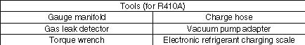
1.5. Using R410A refrigerant air to water heat pump
 Caution:
- Use only R410A refrigerant. If another refrigerant is used, the chlorine will • Be sure to use the proper tools. If dust, debris, or moisture enters the relet the oil deteriorate. frigerant pipes, the refrigeration oil may deteriorate.
- Use the following tools specifically designed for R410A refrigerant use. • Do not use a charging cylinder. If a charging cylinder is used, the compo-Contact your nearest installer for further details. sition of the refrigerant may change and the efficiency will be worsened.
2. Installation location
(mm) 2.1. Choosing the outdoor unit installation location
• Avoid locations where the unit is exposed to direct sunlight or other sources of heat.
 • Select a location where noise emitted by the unit does not disturb neighbors.
- Select a location where easy wiring and pipe access to the power source is available.
- Avoid locations where combustible gases may leak, be produced, flow, or accumulate.
- Note that condensate water may be produced by the unit during operation.
- Select a level location that can bear the weight and vibration of the unit.
- Avoid locations where the unit can be covered with snow. In areas where heavy snow fall is anticipated, special precautions must be taken to prevent the snow from blocking the air intake such as to install the unit at higher position or installing a hood on the air intake. This can reduce the airflow and the unit may not operate properly.
- Avoid locations where the unit is exposed to oil, steam, or sulfuric gas.
- Make sure to hold the handles to transport the unit. Do not hold the base of the unit, as there is a risk that hands or fingers may be pinched.
2.2. Outline dimensions (Outdoor unit) (Fig. 2-1)
Fig. 2-1
2.3. Pipework Installation
- All external pipework shall be insulated to ensure minimal thermal heat loss and also weather protection. Mineral wool insulation (internal diameter 22mm, thermal conductivity 0.04W/m.K) shall be used along with Plysolene sheeting (PIB) to wrap around for weather protection.
- All field supplied pipework must be connected to the heat pump boiler by using QTY2 600mm 1” bore steel braided rubber lined pipes, one for flow and one for return, supplied with the unit. Pipework between the unit and the hot water tank shall be 1”. Provision shall be taken to avoid this pipework freezing during winter months.
- Under some operating conditions, condensate water may be produced which will drain away from the unit. If this is likely to cause a problem (eg. due to freezing on a pathway), we suggest incorporating a 150mm wide by 50mm deep gravel filled channel as a soakaway, or a similar arrangement to suit the location.
INSTALLATION MANUAL


2. Installation location
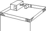
Fig. 2-2

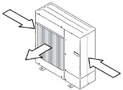
Fig. 2-4
2.4.
2.3. Windy location installation
2.4. NECESSARY SPACE TO INSTALL
2.5.
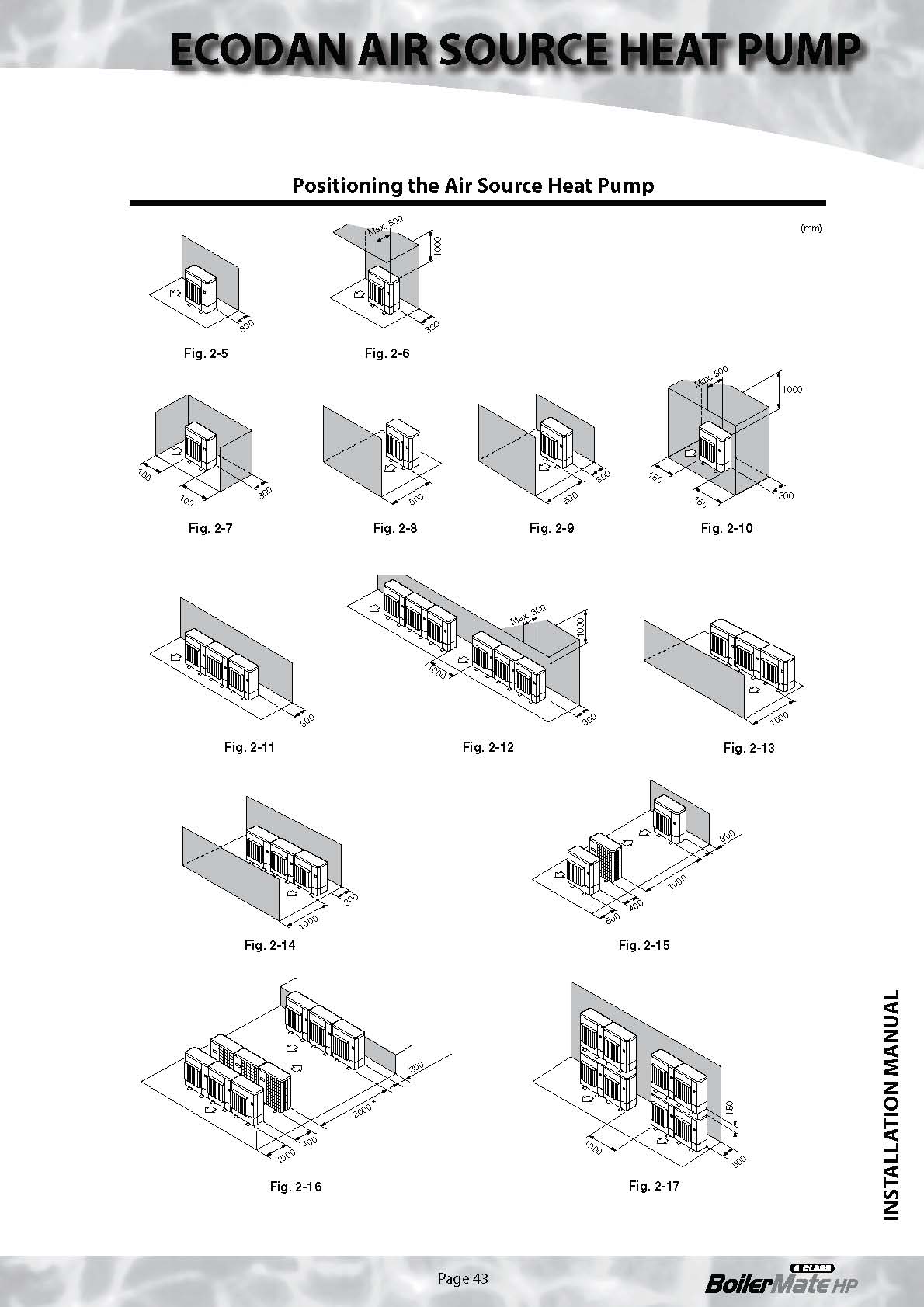
2.4.1. When installing a single outdoor unit (Refer to the last page)
2.5.1.
Minimum dimensions are as follows, unless Maximum dimensions are indicated. Refer to the figures for each case.
1Obstacles at rear only (Fig. 2-5)
2Obstacles at rear and above only (Fig. 2-6)
3Obstacles at rear and side(s) only (Fig. 2-7)
4Obstacles at front only (Fig. 2-8)
5Obstacles at front and rear only (Fig. 2-9)
6Obstacles at rear, side(s), and above only (Fig. 2-10)
• Do not install the optional air outlet guide to make upward airflow.
2.4.2. When installing multiple outdoor units (Refer to the last page)
2.5.2.
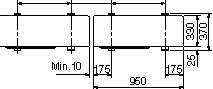
Leave 10 mm or more between the units. 1Obstacles at rear only (Fig. 2-11) 2Obstacles at rear and above only (Fig. 2-12)
- No more than three units must be installed side by side. Make sure to leave space as shown.
- Do not install the optional air outlet guide to make upward airflow. 3Obstacles at front only (Fig. 2-13) 4Obstacles at front and rear only (Fig. 2-14) 5When multiple units are installed in a row (Fig. 2-15) 6When multiple units are installed in rows parallel (Fig. 2-16)
* When using an optional air outlet guide installed to make upward airflow, the necessary dis
tance is 1000 mm or more. 7To stack the unit vertically (Fig. 2-17)
- The units can be stacked up to two units high.
- No more than two stacked units must be installed side by side. Make sure to leave space as
| When installing the outdoor unit on a rooftop or other location where the unit is | shown. |
| exposed to strong wind, do not face the air outlet of the unit directly winds. Strong | |
| wind entering the air outlet may impede the normal airflow and it may result in a | |
| malfunction. | |
| The following shows three examples of precautions against strong winds. | |
| 1Face the air outlet towards the nearest available wall keeping about 50 cm dis | |
| tance. (Fig. 2-2) | |
| 2Install an optional air guide if the unit is installed in a location where strong winds | |
| such as a typhoon, etc. may directly blow to the air outlet. (Fig. 2-3) | |
| � Air outlet guide | |
| 3Position the unit so that the outlet air can blow at right angle to the seasonal | |
| wind direction, if possible. (Fig. 2-4) | |
| � Wind direction | |
| 3. Installation procedure | |
| (mm) | • Be sure to install the unit in a solid, level surface to prevent rattling noises during operation. (Fig. 3-1) |
Foundation bolt Thickness of concrete Length of bolt Weight-bearing capacity
M10 (3/8")
120 mm
70 mm
320 kg
- Make sure that the length of the foundation bolt is within 30 mm from the surface of the base.
- Secure the base of the unit firmly with four-M10 foundation bolts in solid locations.
Installing the outdoor unit
- Do not block the vent. If the vent is blocked, operation will be hindered and the unit may breakdown.
- If the additional fixation of the unit is necessary, use the installation holes on the back of the unit to attach wires, etc. with self-tapping screws (ø5 × 15 mm or less).
 Warning:
• The unit must be securely installed on a structure that can sustain its weight. If the unit is mounted on an unstable structure, it may fall down and
INSTALLATION MANUAL
�����
��� �������� ���
cause damage or injuries.
• The unit must be installed according to the instructions in order to minimize the risk of damage by earthquakes, typhoons, or strong winds. An improperly installed unit may fall down and cause damage or injuries.
 Anti-vibration mats should be used when the unit is mounted on wall brackets. Provision for condensate removal may need to be considered. Under some operating conditions, condensate water may be produced
which will drain away from the unit. If this is likely to cause a problem (eg. due to freezing on a pathway), we suggest incorporating a 150mm wide by 50mm deep gravel filled channel as a soakaway, or a similar arrangement to suit the location.
Fig. 3-1


7. Test run
Before test run
 After installation works are completed, check if there is no refrigerant leak-
age, no looseness in the power supply or control wiring, no wrong polarity,
and no disconnection of one phase in the supply.
Use a 500-volt megohmmeter to check that the resistance between the
power supply terminals and ground is at least 1.0M
After installation works are completed, check if there is no refrigerant leak-
age, no looseness in the power supply or control wiring, no wrong polarity,
and no disconnection of one phase in the supply.
Use a 500-volt megohmmeter to check that the resistance between the
power supply terminals and ground is at least 1.0M

 Warning:
Do not use the air to water heat pump if the insulation resistance is less than
1.0M
Warning:
Do not use the air to water heat pump if the insulation resistance is less than
1.0M

Insulation resistance
When installed the power source to the unit has been cut for an extended period, the insulation resistance may drop below 1 M  due to the accumulation of refrigerant within the compressor. This is not a malfunction. Perform the following procedures.
- Remove the wires from the compressor and measure the insulation resistance of the compressor.
- If the insulation resistance is below 1 M ply the accumulation of refrigerant in the compressor makes the resistance drop.

3. After connecting the wires to the compressor, the compressor starts to warm up once power is supplied. After supplying power for the times indicated below, measure the insulation resistance again.
• The insulation resistance drops due to the accumulation of refrigerant in the compressor. The resistance will rise above 1 M
 after the compressor is warmed up for four hours. (The necessary time to warm up the compressor varies according to atmospheric conditions and refrigerant accumulation.)
• If the refrigerant accumulates within the compressor, the compressor must be warmed up at least 12 hours before starting the operation to prevent breakdown.
4. If the insulation resistance rises above 1 M

 Caution:
- The compressor does not operate if the power supply phase connection is incorrect.
- Turn on the power at least 12 hours before starting operation.
-Starting operation immediately after turning on the main power switch can result in severe damage to internal parts. Keep the power switch turned on during the operating period.
This product is designed and intended for use in the residential, commercial and light-industrial environment.
The product at hand is • Low Voltage Directive 2006/95/ EC based on the following • Electromagnetic Compatibility Directive 89/ EU regulations: 336/ EEC
INSTALLATION MANUAL


HEAD OFFICE: TOKYO BLDG., 2-7-3, MARUNOUCHI, CHIYODA-KU, TOKYO 100-8310, JAPAN


Water Heating Unit PQFY-VRF
INSTALLATION MANUAL

For safe and correct use, read this manual thoroughly before installing the unit.
Available from www.gledhill.net/downloads
Mitsubishi Water Heating Unit Installation Manual - PQFY Mitsubishi Water Heating Control Box Installation Manual - PQFY Procon ACH1


See www.mitsubishi-aircon.co.uk for full details on the PQFY.
It is possible to use the BoilerMate HP to provide either hot water only, or potentially both hot water and heating by connecting to a Mitsubishi PQFY-VRF unit.
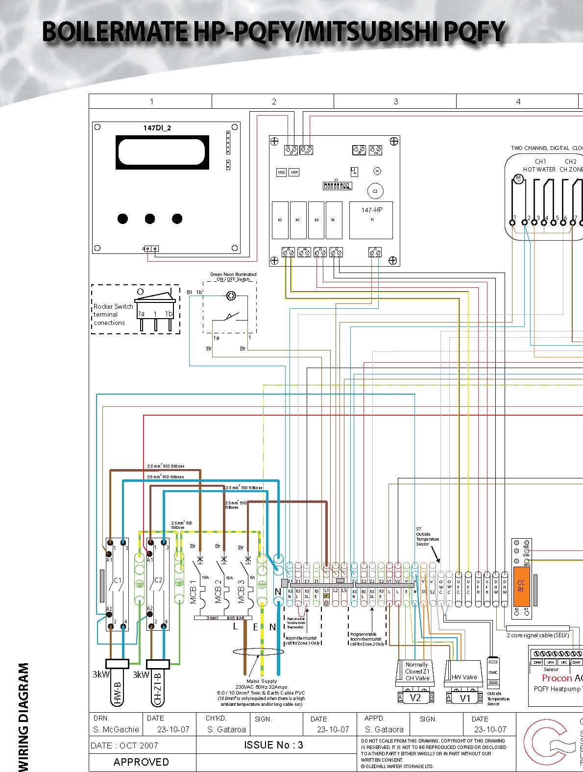
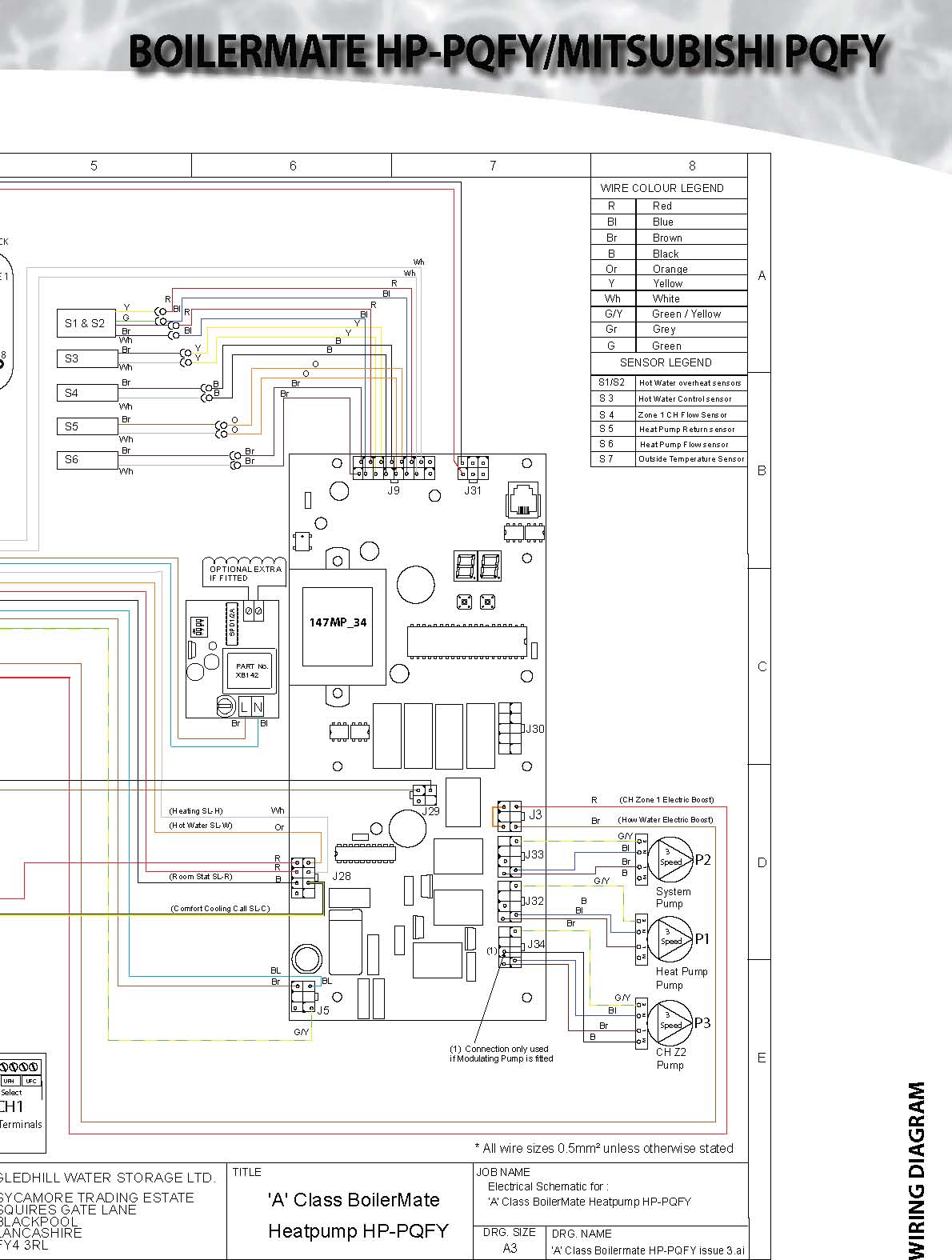
If using with the PQFY-VRF model,please note that it is essential to use the correct BoilerMate HP-PQFY type appliance:
- BMA 180 HP-PQFY
- BMA 210 HP-PQFY
• BMA 240 HP-PQFY See below for the hydraulic and electrical connections.
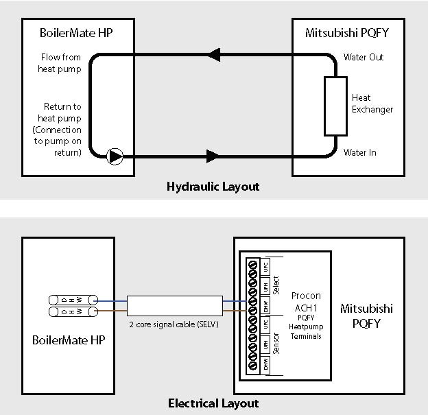
See next page for full electrical schematic diagram.
See previous sections of this BoilerMate HP manual for all other details.
INSTALLATION MANUAL


Page 46


Designed to complement Fernox’s extensive range of chemical water treatment products, the Boiler Buddy is a premium quality in-line, high efficiency magnetic filter with patented flux plates developed for use in Formula 1 motor racing. Unlike other conventional or magnetic filters, Boiler Buddy not only traps magnetite to sub-micron levels, it does so without restricting the water flow, even when full.
Boiler Buddy also offers a unique opportunity for condition monitoring of the system.
Its transparent housing enables the build-up of debris to be observed; acting as an early
warning sign of inherent problems which might result in pumps or valves seizing and
INSTALLATION MANUAL

The Boiler Buddy can be connected directly to 22 mm copper pipework using conventional pump connectors (it is also compatible with 15 mm with the appropriate adapter. It is not recommended for 28 mm systems, as it will restrict the water flow) Boiler Buddy can be installed vertically or horizontally. The unit is designed to slot into the space provided after removing a circulator pump when fitting a condensing boiler into an existing system (ideally it should be fitted on the return close to the boiler itself.) The off-set inlet and outlet ports enable Boiler Buddy to be fitted flush against a wall in existing pipework. System cleaning can be undertaken when a Boiler Buddy is installed by simply isolating and removing the unit at the connection points and powerflushing across the connections.


Boiler Buddy has a transparent body casing so that the build-up of contamination on the core can be observed in service. It has been designed to be fitted where it can be inspected and removed for cleaning and should be installed in the central heating return line as close to the boiler as possible.
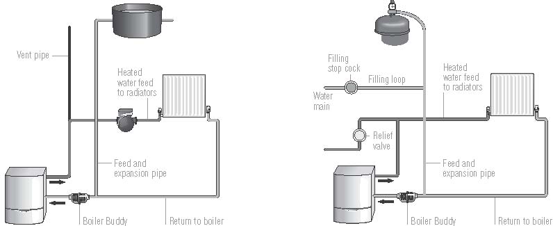
There are a variety of installations but in general the open-vented system and the sealed system are typical.
Feed and expansion tank Expansion vessel

- When selecting a position to install a Boiler Buddy is removed from joints and does not enter the water beware of electrical connections in the vicinity, as these pipework. If soldered joints are being used to construct will be hazardous if they come into contact with water. the pipework, ensure solder or flux is wiped away to
- Install the Boiler Buddy with both an upstream and avoid corroding plastic parts. Do NOT undertake any downstream servicing valve. soldering while the Boiler Buddy is in the pipework.
- Boiler Buddy is designed for use with standard 11/2" BSP Boiler Buddy MUST be removed before soldering x 22 mm pump servicing valves (on a 15 mm system we any joints. recommend fitting 22 to 15 mm reducing sets instead of ■ Once installed, secure the tamper-proof tag to avoid
- three 22 mm olive in the pump servicing valves). accidental opening. The tag must be replaced after
- Boiler Buddy has a face-to-face dimension of 130 mm. cleaning the core.
- If standard pump servicing valves are used, a total ■ Complete the Boiler Buddy installation sticker and apply space of 250 mm is required for installation. to the boiler.
- During installation ensure that all copper or plastic swarf ■ Run the system and check for leaks.
- The Boiler Buddy has no moving parts and needs no ■ It is recommended the Boiler Buddy is inspected and adjustment once in service. cleaned annually.
- The body casing is transparent so that build-up of ■ Boiler Buddy is designed to last the life of the central contamination can be observed. heating system. More frequent cleaning of the core is an
- It is normal for the magnet nearest the inlet of the indication that the system has not been treated correctly Boiler Buddy to become full first. Once this is full the with Fernox Protectors, Restorers and cleansers. next magnet will clog up followed by the next and so

on. The Boiler Buddy has six magnets, we recommend
cleaning the core when three magnets become full.
INSTALLATION MANUAL