|
Diagnosis
|
Abnormality /
|
Diagnosis Method
|
Diagnosis Checkpoint
|
|
Display
|
Protection Control
|
|
|
|
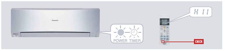
H11
|
Indoor/Outdoor
|
This trouble display appears when indoor/outdoor unit communication
fails to be established after 30 or more
|
Measure the voltages of the indoor/outdoor unit communication cables,
and check whether the voltage is being
|
| |
abnormal
|
seconds.
|
supplied properly to the outdoor unit or whether it is being returned
from the outdoor unit to the indoor units.
|
| |
communication
|
|
|
|
H12
|
Indoor unit capacity
|
This trouble display appears when wrong in the total connection
capacity and wrong connection in each capacity.
|
Check the total capacity of the units connected and check that the
models are compatible for connection.
|
| |
unmatched
|
The trouble is determined within 2 minutes after the power is turned
on.
|
|
|
H14
|
Intake air temp.
|
This trouble display appears when the intake air temperature has
exceeded above 46ºC continuously for 2 minutes
|
This trouble display appears when a temperature which is impossibly
high or low from a normal standpoint has
|
| |
sensor
|
or dropped below -54ºC continuously for 5 seconds during operation.
|
been detected. Check the sensor, and if open-circuiting (0L or ∞)
or short-circuit is not found, defective contact of
|
| |
|
|
the connector is to blame.
|
|
H15
|
Outdoor compressor
|
—
|
Check the sensor, and if open-circuit (more than 500 k) or
(short-circuit) (less than 6.5 k) is not found, defective
|
| |
temperature sensor
|
|
contact of the connector is to blame.
|
| |
abnormality
|
|
|
|
H16
|
Outdoor Current
|
CU-2E: When a value of under 1.5A has been detected for the total
current during operation beyond the set
|
1. Check the refrigerant cycle: Gas may be leaking (the amount of
refrigerant is extremely low).
|
| |
Transformer
|
capacity, the compressor operates with its operating frequency
controlled to a maximum of 38Hz for 3 minutes,
|
2. Check the control PCB: Check for a broken wire (open circuit) in the
current transformer. (If an open circuit is
|
| |
|
and if it continues to operate at a total current of under 1.5A for
another 3 minutes, its operation stops.
|
found, replace the control PCB) In the case of a scroll compressor (DC
motor), H16 is detected only when the
|
| |
|
CU-3E/4E: When the total current has dropped below the set current
level continuously for 20 seconds during
|
regular compressor is operating.
|
| |
|
operation beyond the set capacity, operation is stopped. Three minutes
later, operation is started up again, and
|
|
| |
|
when the trouble occurs on 4 successive occasions, the trouble display
appears (the timer lamp blinks).
|
|
|
H19
|
Indoor fan motor
|
· High-voltage PWM: When a state in which the fan motor speed is not
synchronized with the control signal has been
|
1. Check the nature of the fan lockup trouble.
|
| |
mechanism lock
|
detected on 7 successive occasions.
|
2. Check for disconnections of the fan motor connectors and for defects
in contact, in the fan motor and in the
|
| |
|
· Low-voltage PAM: When the fan lock detection signal has been
detected on 7 successive occasions or it has been
|
control PCB.
|
| |
|
detected continuously for 25 seconds or when a state in which the fan
motor speed is not synchronized with the control
|
|
| |
|
signal has been detected on 7 successive occasions: The trouble display
appears (the timer lamp blinks).
|
|
|
H23
|
Indoor heat exchanger
|
This trouble display appears when a temperature of under approximately
-40ºC or above approximately 80ºC has
|
This trouble display appears when a temperature which is impossibly
high or low from a normal standpoint has
|
| |
temp. sensor
|
been detected by the heat exchanger temperature sensor continuously for
5 seconds. (This trouble is not detected
|
been detected. Check the sensor, and if (open-circuit) (0L or ∞)
or short-circuit is not found, defective contact of
|
| |
|
during de-icing.)
|
the connector or a defective control PCB is to blame.
|
|
H26
|
Ionizer Abnormality
|
—
|
1. Measure the voltages of the indoor unit communication cables, and
check whether the voltage is being supplied
|
| |
|
|
properly. 2. Check the ionizer needle and grounding plate is dust free.
|
|
H27
|
Outdoor air temp.
|
This trouble display appears when a temperature of under approximately
-40ºC or above approximately 150ºC has
|
This trouble display appears when a temperature which is impossibly
high or low from a normal standpoint has
|
| |
sensor
|
been detected by the outside air temperature sensor for 2 to 5 seconds.
(This trouble is not detected during
|
been detected. Check the sensor, and if open-circuiting (0L or ∞)
or short-circuit isnot found, defective contact of
|
| |
|
de-icing.)
|
the connector or a defective control PCB is to blame.
|
|
H28
|
Outdoor heat
|
This trouble display appears when a temperature of under approximately
-60ºC or above approximately 110ºC has
|
This trouble display appears when a temperature which is impossibly
high or low from a normal standpoint has
|
| |
exchanger temp.
|
been detected by the heat exchanger temperature sensor for 2 to 5
seconds. (This trouble is not detected during
|
been detected. Check the sensor, and if open-circuiting (0L or ∞)
or short-circuit is not found, defective contact of
|
| |
sensor 1
|
de-icing.)
|
the connector or a defective control PCB is to blame.
|
|
H30
|
Outdoor discharge
|
CU-2E: This trouble display appears when a temperature of under
approximately -16ºC or above approximately
|
This trouble display appears when a temperature which is impossibly
high or low from a normal standpoint has
|
| |
pipe temp. sensor
|
200ºC has been detected by the outlet temperature sensor for 2 to 5
seconds.
|
been detected. Check the sensor, and if open-circuiting (0L or ∞)
or short-circuit is not found, defective contact of
|
| |
|
CU-3E/4E: Disconnected discharge sensor · When the condensation
temperature is higher than the discharge
|
the connector or a defective control PCB is to blame.
|
| |
|
temperature + (plus) 6ºC, a sensor disconnection is detected,
operation stops, and the trouble display appears
|
|
| |
|
(the timer lamp blinks).
|
|
|
H32
|
Outdoor heat exchanger
|
This trouble display appears when a temperature of under approximately
-60ºC or over approximately 110ºC has
|
This trouble display appears when a temperature which is impossibly
high or low from a normal standpoint has
|
| |
temp. sensor 2
|
been detected continuously for 2 to 5 seconds by the outlet temperature
sensor of the heat exchanger.
|
been detected. Check the sensor, and if open-circuiting (0L or ∞)
or short-circuit is not found, defective contact of
|
| |
(discharge pipe temp.)
|
|
the connector or a defective control PCB is to blame.
|
|
H33
|
Indoor / Outdoor
|
Indoor / Outdoor different model junction, 100V charge into 200V
outdoor unit.
|
Check whether the voltage is being supplied properly to the outdoor
unit or whether it is being returned from the
|
| |
wrong connection
|
|
outdoor unit to the indoor units.
|
|
H34
|
Outdoor heat sink
|
This trouble display appears when a temperature of under -43ºC or
above 80ºC has been detected by the outdoor
|
This trouble display appears when a temperature which is impossibly
high or low from a normal standpoint has
|
| |
temp. sensor
|
unit radiator fin sensor continuously for 2 seconds.
|
been detected. Check the sensor, and if open-circuiting (0L or ∞)
or short-circuit is not found, defective contact of
|
| |
|
|
the connector or a defective control PCB is to blame.
|
|
H36
|
Abnormal gas pipe
|
This trouble display appears when a temperature of under approximately
-45ºC or above approximately 149ºC has
|
This trouble display appears when a temperature which is impossibly
high or low from a normal standpoint has
|
| |
temp. sensor
|
been detected by the outdoor unit gas side pipe temperature sensor
continuously for 2 to 5 seconds.
|
been detected. Check the sensor, and if open-circuiting (0L or ∞)
or short-circuit is not found, defective contact of
|
| |
|
|
the connector or a defective control PCB is to blame.
|
|
H37
|
Outdoor liquid pipe
|
This trouble display appears when a temperature of under -45ºC or
above 149ºC has been detected by the outdoor
|
This trouble display appears when a temperature which is impossibly
high or low from a normal standpoint has
|
| |
temp. sensor
|
unit liquid side pipe temperature sensor continuously for 2 seconds.
|
been detected. Check the sensor, and if open-circuiting (0L or ∞)
or short-circuit is not found, defective contact of
|
| |
|
|
the connector or a defective control PCB is to blame.
|
|
H38
|
Indoor / Outdoor
|
—
|
—
|
| |
mismatch (brand code)
|
|
|
|
H39
|
Abnormal indoor
|
This display appears in rooms other than one in which indoor freezing
trouble has occurred when the pipes have
|
—
|
| |
operating unit or
|
been connected incorrectly, when an outdoor expansion valve is
defective or when an expansion valve connector
|
|
| |
standBy units
|
has become disconnected.
|
|
|
H41
|
Abnormal wiring or
|
CU-2E only This display appears when this kind of trouble is detected 3
minutes after a forced cooling operation
|
—
|
| |
piping connection
|
was conducted for one room during the initial operation after the power
was turned on. It appears when:
|
|
| |
|
· The indoor unit pipe temperature in a room without the capacity
supply available at an outside air temperature
|
|
| |
|
above 5ºC has dropped by more than 20ºC to 5ºC or lower 3 minutes
after the compressor started up. · The
|
|
| |
|
outdoor unit gas pipe temperature in a room without the capacity supply
available has dropped by more than 5ºC
|
|
| |
|
to 5ºC or lower 3 minutes after the compressor started up.
|
|
|
H50
|
Ventilation failure
|
This display appears when ventilation motor is lock.
|
1. Check the voltage drop at pin 1 & 2 of CNVENT to have 14Vdc. 2.
Check the ventilation hose condition from
|
| |
|
|
ventilation opening until tip cover. 3. Check air fl ow from tip cover
by hand.
|